Copyright Michael Karbo and ELI Aps., Denmark, Europe.
Chapter 2. The Von Neumann model
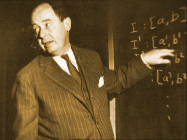
The modern
microcomputer has roots going back to
Von Neumann divided a computer’s hardware into 5 primary groups:
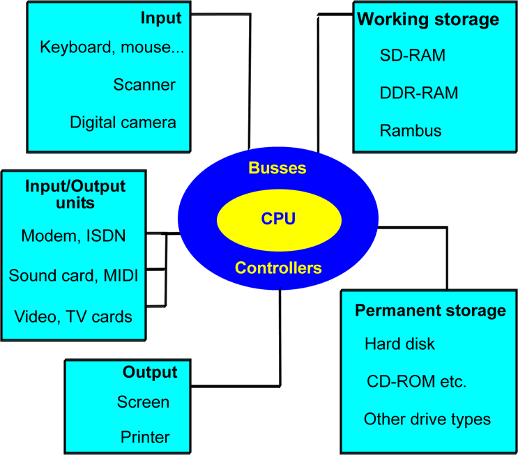
This division provided the actual foundation for the modern PC, as von Neumann was the first person to construct a computer which had working storage (what we today call RAM). And the amazing thing is, his model is still completely applicable today. If we apply the von Neumann model to today’s PC, it looks like this:
 Fig. 11. The Von Neumann model in the year 2004.
 Fig. 12. Cray supercomputer, 1976.
In April 2002 I read that the Japanese had developed the world’s fastest computer. It is a huge thing (the size of four tennis courts), which can execute 35.6 billion mathematical operations per second. That’s five times as many as the previous record holder, a supercomputer from IBM.
The report
from
2. The PC’s system components
This chapter is going to introduce a number of the concepts which you have to know in order to understand the PC’s architecture. I will start with a short glossary, followed by a brief description of the components which will be the subject of the rest of this guide, and which are shown in Fig. 11.
The necessary concepts
I’m soon going to start throwing words around like: interface, controller and protocol. These aren’t arbitrary words. In order to understand the transport of data inside the PC we need to agree on various jargon terms. I have explained a handful of them below. See also the glossary in the back of the guide.
The concepts below are quite central. They will be explained in more detail later in the guide, but start by reading these brief explanations.
|
Concept |
|
|
Binary data |
Data, be it instructions, user data or something else, which has been translated into sequences of 0’s and 1’s. |
|
Bus width |
The size of the packet of data which is processed (e.g. moved) in each work cycle. This can be 8, 16, 32, 64, 128 or 256 bits. |
|
Band width |
The data transfer capacity. This is measured in, for example, kilobits/second (Kbps) or megabytes/second (MBps). |
|
Cache |
A temporary storage, a buffer. |
|
Chipset |
A collection of one or more controllers. Many of the motherboard’s controllers are gathered together into a chipset, which is normally made up of a north bridge and a south bridge. |
|
Controller |
A circuit which controls one or more hardware components. The controller is often part of the interface. |
|
Hubs |
This expression is often used in relation to chipset design, where the two north and south bridge controllers are called hubs in modern design. |
|
Interface |
A system which can transfer data from one component (or subsystem) to another. An interface connects two components (e.g. a hard disk and a motherboard). Interfaces are responsible for the exchange of data between two components. At the physical level they consist of both software and hardware elements. |
|
I/O units |
Components like mice, keyboards, serial and parallel ports, screens, network and other cards, along with USB, firewire and SCSI controllers, etc. |
|
Clock frequency |
The
rate at which data is transferred, which varies quite a lot between the
various components of the PC. |
|
Clock tick (or clock cycle) |
A single clock tick is the smallest measure in the working cycle. A working cycle (e.g. the transport of a portion of data) can be executed over a period of about 5 clock ticks (it “costs” 5 clock cycles). |
|
Logic |
An expression I use to refer to software built into chips and controllers. E.g. an EIDE controller has its own “logic”, and the motherboard’s BIOS is “logic”. |
|
MHz |
A ”speed” which is used to indicate clock frequency. It really means: million cycles per second. The more MHZ, the more data operations can be performed per second. |
|
North bridge |
A chip on the motherboard which serves as a controller for the data traffic close to the CPU. It interfaces with the CPU through the Front Side Bus (FSB) and with the memory through the memory bus. |
|
Protocols |
Electronic traffic rules which regulate the flow of data between two components or systems. Protocols form part of interfaces. |
|
South bridge |
A chip on the motherboard which works together with the north bridge. It looks after the data traffic which is remote from the CPU (I/O traffic). |
Fig. 13. These central concepts will be used again and again. See also the definitions on page PAGEREF Ordforklaringer2 \h 95.
