4.10.2 State-Transition-Diagram Approach to Networks with Blocking Effects
Whenever the arrival of users at a queueing
network constitutes a Poisson process and each queueing system in the network has negative
exponential service times, it is possible, at least in principle, to obtain the
properties of the queueing network under steady-state conditions by using the following
twostep approach:
STEP 1: Prepare a state-transition diagram that shows all the possible states that the
queueing
network
(i.e., the collection of queueing systems) can be in and the transitions between
states in
steady state.
STEP 2: Write and solve the balance equations for the steady-state probabilities of the
queueing network.
This approach will be one of the fundamental
ideas that Chapter 5 will develop with respect to a specific but very rich family of
queueing systems. In this section we shall only illustrate the approach with reference to
series queueing networks with blocking effects. One of the main points that the
reader should take note of is how this approach can deal with interactions between the
component queueing systems of the network.
Example 3: In-Series Servers with No Waiting Space
Consider the queueing network shown in Figure 4.19. Arrivals at the first facility are
Poisson with rate  . The two facilities contain single identical servers with
negative exponential service times and mean service time 1 / . The two facilities contain single identical servers with
negative exponential service times and mean service time 1 / . No queues are allowed in front of
facility 1 or between the two facilities. Thus, facility 1 is "blocked" whenever
it has completed service to a user while facility 2 is occupied with another user. As a
result, prospective users of the queueing network are turned away not only when, on
arrival, they find facility 1 busy, but also when they find it blocked. . No queues are allowed in front of
facility 1 or between the two facilities. Thus, facility 1 is "blocked" whenever
it has completed service to a user while facility 2 is occupied with another user. As a
result, prospective users of the queueing network are turned away not only when, on
arrival, they find facility 1 busy, but also when they find it blocked.

Solution
To describe the state of the network we now need two index numbers: one to indicate the
state of facility 1 and the second to indicate the state of facility 2. Facility 2 can be
either empty (0 users in the facility) or contain 1 user; facility 1 can be empty (0
users) or full and busy (1 user) or idle but full due to blocking from another user in
facility 2. We indicate this last condition by the letter b, for "blocked."
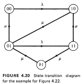
Thus, the possible network states are 00, 01, 10, 11, and b1, with the first index number,
by convention, denoting the state of facility 1. Note that state b0 cannot exist.
A state-transition diagram for the network of
Figure 4.19 is now shown in Figure 4.20. Using the diagram and recalling the "rate
in" = "rate out" approach that we have taken in order to write steady-state
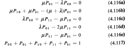
equations of balance, we have

where the meaning of each of the steady-state probabilities Pij
is obvious.

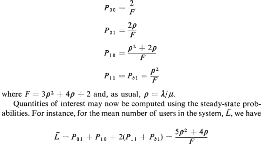
Using (4.117) and any four of the five
equations in (4.116) and solving for the five steady-state probabilities, we obtain

Of more interest, however, are the effects
of blocking (and of the zero queueing capacity) on the performance of the queueing
network. For example, the mean number of busy servers in the network is

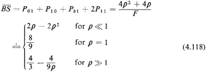
while the fraction of potential users lost is given by

It is interesting to observe how  and f
change as additional queueing slots are provided in front of one or both service
facilities. and f
change as additional queueing slots are provided in front of one or both service
facilities.
Theoretically, this type of
approach can, as noted above, be applied to any queueing network-no matter how complex-as
long as the queue capacities for every element of the network are finite. 16
When all queue capacities are finite, there is a finite number of possible network states
and, consequently, a finite number of balance equations which determine the steady-state
probabilities (see Problem 4.13).
In practice, however, the number of states increases
rapidly with the number of network elements, while the writing and solving of steady-state
balance equations turns progressively more difficult as the complexity of network
topologies increases. To appreciate this, imagine the simple network of Figure 4.19 but
extended by two more facilities in series: thus, we have an in-series network consisting
of four single-server facilities with no queueing slots available in front of the first
service facility or in the space between facilities. It then turns out that a full 34
different network states exist, with each state requiring four index numbers (one for each
of the four servers).
The approach can also be applied to networks where
some or all queue capacities are infinite. However, the number of balance equations is
also infinite in this case, since we must write one balance equation for each state. Under
these conditions it is possible to obtain closed-form solutions for the steady-state
probabilities only if some type of "structure" is detected in the infinite
equations. [We did observe such structures in our discussion of birth-and- death queueing
systems (Sections 4.5 and 4.6) and were thus able to solve a system with an infinite
number of balance equations.] The hypercube queueing model, which is presented in Chapter
5, is an excellent example of a queueing system in which this structure-detection approach
applies.
16 Remember that this discussion assumes
Poisson arrivals at the network and negative exponential service times for all servers. |