Answers Database
M1.4 LogiBLOX: How to constrain a 4KE/X LogiBLOX Counter

Record #3482

Product Family:  Software

Product Line:  Merged Core

Problem Title:
M1.4 LogiBLOX: How to constrain a 4KE/X LogiBLOX Counter


Problem Description:
Keywords: logiblox, counter, loc

Urgency: standard


How do you LOC a LogiBLOX counter to a region of the die?

The LogiBLOX counter for the 4000E/EX/XL can be LOC'd
to a particular region of the FPGA via the RLOC_ORIGIN
constraint. It is not advisable to use a LOC; this
will be explained below.

The method by which we constrain the LogiBLOX will
differ depending on how large the counter is.
The main difference is that counters of more than 4 bits
will use carry logic; counters with 4 or less bit will
not.
Remember that timespecs are still the best way of getting
the best timing in most cases; use physical placement
constraints only as a last resort.


Solution 1:

FOR COUNTERS WITH MORE THAN 4 BITS
==================================

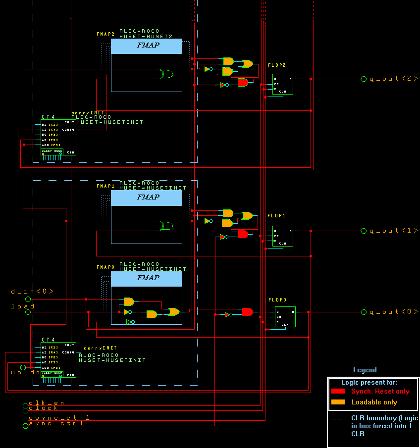
The following is a visual representation of the LogiBLOX
counter, assuming that most features are active (sync_ctrl,
async_ctrl, enable, loadable):


4KE LogiBLOX counter (more than 4 bits)

You will notice that the flop names are FLOP0, FLOP1, FLOP2,...
with FLOP0 being the register for the LSB (q_out<0>). The
carry logic is similiarly named, except for the LSB bit. Also,
there is one CY4 (carry logic module) per CLB (and two flops
per CLB), so the carrys are named: carryINIT, carry2, carry4,..


	    FMAP7   FLOP7
carry6	    FMAP6   FLOP6
-----------------
	    FMAP5   FLOP5
carry4	    FMAP4   FLOP4
-----------------
	    FMAP3   FLOP3
carry2	    FMAP2   FLOP2
-----------------
	    FMAP1   FLOP1
carryINIT   FMAP0   FLOP0

In order to lock it down, you must use a RLOC_ORIGIN.
In order for this to work correctly, you must attach a
RLOC_ORIGIN to *all* the carry logic modules. The following
is an example. Assume the instance name of the counter
in schematic/HDL is $1I4:

##This is example for 8-bit counter with Terminal Count
INST $1I4/carryINIT RLOC_ORIGIN=R10C10;
INST $1I4/carry2    RLOC_ORIGIN=R9C10;
INST $1I4/carry4    RLOC_ORIGIN=R8C10;
INST $1I4/carry6    RLOC_ORIGIN=R7C10;
INST $1I4/carry8    RLOC_ORIGIN=R6C10; ##only if using TC!!!

Remember, if you are using the Terminal Count, there is an
additional carry logic module that must be RLOC_ORIGINed.

-------------------------------------------------------
The following is an explanation of why RLOC_ORIGIN on
all carry logic is necessary.
-------------------------------------------------------

In order to place this on the die at a given location,
we must use the RLOC_ORIGIN constraint. Note that all
the carry logic as well as the FMAPs have RLOCs on them,
but the FLOPs do not. RLOCs are usually used to create
RPMs (Relationally Placed Macros), but in this case, the
RLOC is solely used to pack specified logic into a CLB.
In other words, the RLOC=R0C0 constraint on the FMAP0,1
and carryINIT blocks force these three items to be placed
into a single CLB. It does not force it to be placed
relative to the CLB above it, however. Why? Because each
set of two FMAPs and its associated CY4 have its own
HU_SET, which prevents their RLOCs from "communicating"
with the other RLOCs in the module. But since carry logic is
being used, it is forced into a column anyway(carry logic
must be loaded or sourced by the CLB above or below it).
So there is no need for a RPM for a LogiBLOX counter with more
than 4 bits; carry logic takes care of it.

You could in theory try LOCing the FLOPs (since they
do not have RLOCs, you can LOC them). However, this
will typically cause MAP to seperate the FLOPs from
the rest of the CLB, and you will get an inefficient
mapping. Stick to RLOC_ORIGIN'ing the carry logic.


Solution 2:

FOR COUNTERS WITH 4 BITS OR LESS
==================================

   Counters that have 4 bits or less do not employ carry logic
modules (CY4). Instead, it relies on regular LUTs to generate
the carry. The reason for this is that the number of logic
levels for the LUTs to make a carry is low (for 4 or less bits), and it thus fas
ter than using CY4s (using the carry chain incurs some "overhead", and is best f
or larger counters).
There is no mapping information or RLOCs present.

It is not advisable to attempt to create a RPM out of the
smaller counters. Timing may actually suffer, since aligning
the CLBs into a column is not necessarily the best placement
for a given architecture. However, if LOCing the counter is
still required, then the following will work.

The flops in the counter are one level of hierarchy beneath
the LogiBLOX counter instance. The name of the intermediate
hierarchy level is the same name as the counter instance
or module name. If you invoke lbgui stand-alone, then the
name will be the module name. If you invoke LogiBLOX from
a front end tool (such as Viewlogic), then the name will
be the instance name of the module that you instantiate
into schematic.
The underlying flop names are FLOP0, FLOP1, FLOP2, and FLOP3
(not all will be present if you generate less than 4 bits;
FLOP0 is the LSB).

Example1: Invoke LogiBLOX from Viewlogic, name the module
 "mycounter" in the LogiBLOX GUI, and then name the instance
 "$1I4" in the schematic:


INST $1I4/$1I4/FLOP0 LOC=CLB_R5C5;
INST $1I4/$1I4/FLOP1 LOC=CLB_R5C5;
INST $1I4/$1I4/FLOP2 LOC=CLB_R4C5;
INST $1I4/$1I4/FLOP3 LOC=CLB_R4C5;

Example2: Invoke LogiBLOX from prompt(lbgui), name the module
 "mycounter" in the LogiBLOX GUI, and then name the instance
 "$1I4" in the a schematic tool:


INST $1I4/mycounter/FLOP0 LOC=CLB_R5C5;
INST $1I4/mycounter/FLOP1 LOC=CLB_R5C5;
INST $1I4/mycounter/FLOP2 LOC=CLB_R4C5;
INST $1I4/mycounter/FLOP3 LOC=CLB_R4C5;


Also be warned that attaching LOCs to the FLOPs may in itself
cause MAP to map the logic differently, and usually less
efficiently.


End of Record #3482

| For the latest news, design tips, and patch information on the Xilinx design environment, check out the Xilinx Expert Journals! |


