

|
|
| |
|
Answers Database
FPGA Express 1.2/Foundation 1.3: Creating HDL Macros with FPGA Express 1.2 for Placement on a Foundation 1.3 Top-Level Schematic
Record #3013
Product Family: Software 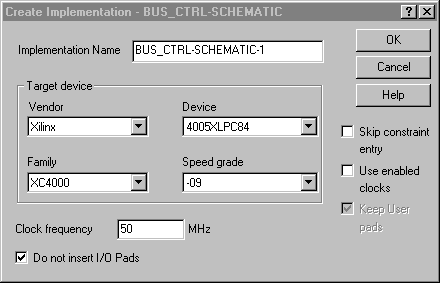 Figure 1- Do not insert I/O pads When performing the 'Export Netlist' step in FPGA Express, browse to the Foundation project directory created above, and save the netlist into this directory. (3) Modify the Netlinst The XNF file created by FPGA Express must be modified to replace all of the 'EXT' records with 'SIG' records. This can be done manually with any text editor. Alternatively, the ext2sig.pl Perl script can perform this function. Please refer to (Xilinx Solution 2843) in the Xilinx Answers Database for more information on this script. (4) Importing the Netlist into a Foundation Schematic IMPORTANT: With Foundation F1.3, there is a bug with the XNF to EDIF translation flow, described in (Xilinx Solution 3330). We recommend following the steps in that solution rather than continuing with this solution for steps 4 through 6. If you are instantiating XNF files without INV properties, continue here. Open the Foundation project created in Step 1. To import the XNF from FPGA Express into the Foundation schematic, select Hierarchy->Import Netlist from the Schematic Editor. This will import the netlist into the Foundation project, and create an associated symbol for placement on the schematic. Connectivity between this symbol and the XNF file is done by name, so do not change the name of one without changing the name of the other. The symbol will be automatically be added to the Foundadtion project library. To place the symbol on the schematic, brows the the 'SC Symbols' list of library components to find the module. The name of the module will be the same as the name of the imported XNF netlist. To bring up the 'SC Symbols' list, click the SC Symbols icon on the vertical toolbar:  Figure 2- SC Symbol Icon (5) Modify the Symbol The symbol for the imported netlist will not have bus pins. If you wish to create bus pins, double-click on the symbol, and then click the 'Symbol Editor' button to invoke the Symbol Editor. Once in the Symbol Editor, bus pins can be created, and the corresponding individual pins may be delted. When naming a bus pin, use the notation BUS_NAME[3:0], where BUS_NAME is the name of the bus, and [3:0] is an example of the bounds of the bus. 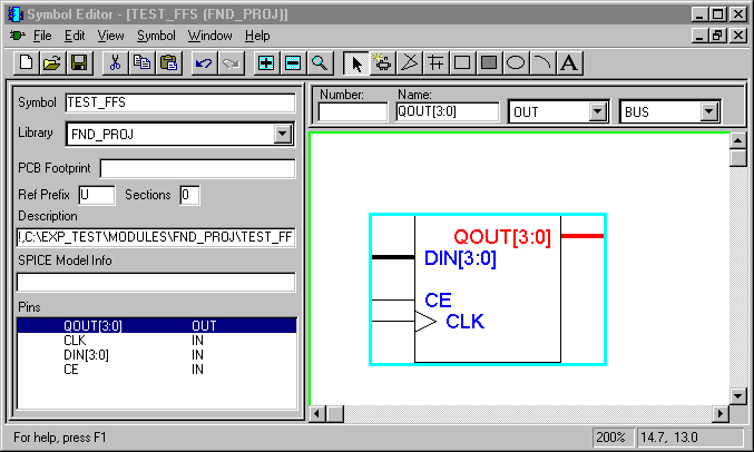 Figure 3- Symbol Editor (6) Simulate the Design To functionally simulate the design, enter the Logic Simulator by clicking the 'SIM Funct' button in the Foundation Project Manager. The design, including the FPGA Express generated XNF netlist, will be loaded into the simulator. To perform timing simulation, follow the Foundation procedures for timing simulation as if the design were a pure schematic. Note: The M1.3 core technology software, like Verilog, is case-sensitive with respect to names. VHDL is not case-sensitive, but the XNF written out by FPGA Express will follow the case-sensitivity used in the Verilog or VHDL code. If case-sensitivity is not followed consitently when making constraints, the M1.3 software may not be able to properly merge FPGA Express v1.2 XNF with EDN files from Foundation 1.3. End of Record #3013 - Last Modified: 08/19/99 09:28 |
| For the latest news, design tips, and patch information on the Xilinx design environment, check out the Technical Tips! |