|
|
 To download
a .pdf copy of this White Paper, click here. To download
a .pdf copy of this White Paper, click here.
Introduction
This white paper gives an overview of ISDN modem technologies and how Xilinx
high volume programmable devices can be used to implement complex system
level glue in ISDN modem designs. The Xilinx device families targeted
at these high volume applications include XC9500
CPLDs and Spartan FPGAs.
The flow of this document will be start with an overview of ISDN technology
and how ISDN modems are used. We will next examine the major functional
blocks of an ISDN modem and give an overview of the Application Specific
Standard Products (ASSPs) that implement ISDN functions. We will
then illustrate the system level glue functions that are needed by way
of a design example.
Overview
ISDN (Integrated Services Digital Network) is a technology that was originally
defined in the mid-80s as a means of delivering integrated voice, data,
and video services to Bell system customers. Although the technology
definitely shows its age, it is still one of the most widely deployed digital
data services.
ISDN is a circuit switched technology. In circuit switching, a
dedicated communications path is established between two stations.
The process of establishing these dedicated paths is referred to as signaling,
and is carried out over special channels referred to as D (Delta) channels.
Signaling results in the establishment of one or more 64 kilobit-per-second
(kbps) B (Bearer) channels between locations. Once established,
these channels can be used for voice, data or video.
There are two main ISDN variants, Basic Rate ISDN (BRI) and Primary Rate
ISDN (PRI). Primary Rate ISDN service is targeted at larger corporate
customers. PRI service consists of 23 B channels in North America
and is transported across a standard T1 physical layer interface.
In Europe the service provides 30 B channels plus one 64 kbps D channel
and uses an E1 physical layer. PRI requires two sets of twisted
pair telephone lines.
Basic Rate ISDN services are targeted at home and small business users.
BRI service is delivered over a single twisted pair, the same wiring that
is used to deliver POTS (Plain Old Telephone Service). It provides
2 B channels and one 16 kbps D channel. For the rest of this paper
the term ISDN will be used synonymously with Basic Rate ISDN.
ISDN Model
The CCITT documentation defines the overall model of ISDN in terms of Reference
Points and Functional Groupings. Figure 1 illustrates
the ISDN Reference Model. |
Figure 1 ISDN Reference Model
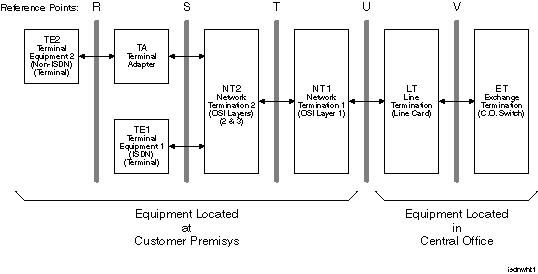
| Functional Groupings define finite arrangements of physical equipment
or combinations of equipment. ISDN defines the following Functional
Groupings:
TE2 (Terminal Equipment 2): TE2 devices are non-ISDN terminal
equipment such as personal computers. These devices interface to
a TA by way of an R interface.
TA (Terminal Adapter): Adapts non-ISDN equipment to ISDN.
A TA provides an R interface for the non-ISDN equipment and an S/T interface
for connection to the ISDN network.
TE1 (Terminal Equipment 1): ISDN terminal equipment such as
ISDN telephones. These devices interface to the ISDN network by
way of an S interface.
NT1 (Network Termination Equipment for layer 1): Equipment that
terminates the ISDN network connection at OSI layer 1 (the physical
layer). Specifically it terminates the U interface and converts
it into an S/T interface.
NT2 (Network Termination Equipment for layer 2): Equipment that
terminates the ISDN network interface at OSI layer 2, (the data link
layer). An example would be a PBX that terminates a PRI connection
and provides several BRI interfaces. An NT2 interfaces to a TA
or TE1 via an S interface and to an NT1 via a T interface.
Reference Points are conceptual points used to separate groups of ISDN function.
Some of these reference points are purely conceptual abstractions while
others are defined as physical interfaces between functional blocks.
ISDN defines the following Reference Points:
R: Provides a non-ISDN interface between user equipment that
is not ISDN capable and ISDN adapter equipment. Examples include
RS232, V.35, and X.21.
S: Interface between Terminal Adapters (TA) or terminal and Network
termination.
T: The interface between an NT1 and NT2. It is functionally
equivalent to the S interface.
U (User): The interface between the ISDN customer premises equipment
and the public ISDN network. This interface defines a point to
point connection using a single twisted pair and 2B1Q data coding.
Some of these Functional Groupings and Reference points apply to equipment located
in the central office while others apply to equipment located on the customer
premises. This paper will focus on the portion of the model that resides
in the customer premises and are applicable to ISDN modems.
U Interface
The U (User) Interface is a point to point connection between subscribers and
the service providers central office. It consists of a single twisted
pair that may be up to 5.5 km in length. Mid-span repeaters can double
this distance.
In order to support transmission over these distances the U Interface
uses some sophisticated transmission technology. A multilevel, 2B1Q
(Two Binary, One Quaternary) line code (4B3T in Europe) is used as well
as adaptive equalization and echo cancellation. In addition a scrambling
polynomial is used to improve clock recovery and improve the spectral
characteristics of the signal on the wire.
S/T Interface
The S/T Interface was defined for interconnecting ISDN customer premises equipment.
As a result the technology employed differs significantly from that of the
U Interface. The S/T Interface supports a bus topology with up to
eight stations. Using four wires it supports a maximum distance of
1 km. The shorter distances involved, and full duplex transmission,
simplify the line coding. An Alternate Space Inversion (ASI) coding
scheme, also referred to as pseudo-ternary scheme, is used.
Proprietary TDM Interfaces
In addition to the interfaces defined in the ISDN specifications, vendors of ISDN
ASSPs have defined several proprietary interfaces for tying together ISDN
devices in a system. A typical application for such an interface is
connecting an S/T interface ASSP to a U interface ASSP to create an NT1.
These interfaces typically consist of four to seven signals. These
signals include a transmission clock, serial data in, serial data out, and
a start of frame indicator.
Several of the key TDM interfaces are as follows:
CHI: Concentration Highway Interface, defined by Lucent.
IOM-2: ISDN Oriented Modular Interface, defined by Infineon
(formerly Siemens) and supported by AMD as part of a second source relationship.
IDL: Inter-chip Digital Link, defined by Motorola.
While several vendors support more than one of these interfaces on their device,
using devices from different vendors often involves using glue logic to
deal with the differences in these interfaces.
ISDN in the Real World
Now that we have had an overview of ISDN technology in the abstract, lets see
how these technologies are packaged in the real world to create ISDN modems.
Figure 2 illustrates how ISDN modems are typically deployed
in Europe and North America. |
Figure 2 ISDN Modem Applications
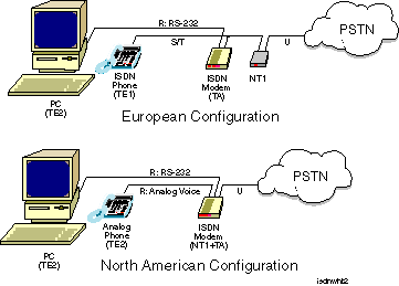
| In Europe the telephone companies do not let subscribers connect their
own equipment directly to the Public Switched Telephone Network (PSTN).
The Telco provides an NT1 to the customer as part of the service package.
In this case the demarcation point between the subscriber and the PSTN is
the S/T interface on the NT1, and the ISDN modem acts as a TA.
In North America, users can connect their own equipment directly to the
PSTN and the demarcation point becomes the U interface. As a result,
ISDN modems for the North American market typically include a built-in
NT1. This lowers cost and simplifies installation.
Another difference between the European and North American configurations
is how voice services are provided. In Europe there was reasonable
acceptance of ISDN telephones. If an ISDN telephone is used it is
simply connected to the S/T interface along with the modem. In North
America ISDN phones are very rare and as a result ISDN modems include
the circuitry necessary to convert digital voice signals into the analog
form used by a standard telephone.
Anatomy of an ISDN Modem
The functional blocks that make up an ISDN modem are a function of whether the
device is an add-in card for a personal computer or a stand-alone unit.
An external modem, or active TA, includes a processor for protocol processing,
logic for the R Interface, and usually a voice COder/DECoder (CODEC).
The inclusion of a CODEC lets the user plug in a standard analog phone
and use it to make voice calls over one of the ISDN B channels.
The R interface is typically RS-232, Ethernet or USB and is implemented
using an ASSP. Figure 3 shows a block diagram
for an external modem.
|
Figure 3 External ISDN Modem
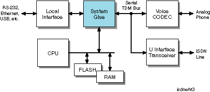
| The system glue has two functions within the architecture. The first
is to normalize interface differences between the functional blocks.
The second is to implement the required ISDN functional groupings.
In this application this means the TA functions required to support the
non-ISDN interfaces, specifically the R interface that embodies the local
side of the modem and the CODEC. TA functions that must be implemented
include Link Access Procedure D Channel (LAPD) framing functions that are
used in signaling and Point to Point Protocol (PPP) or Multilink PPP functions
that are used to transport data from the R interface across the ISDN network.
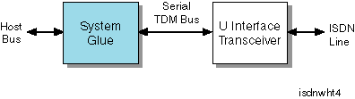
Internal modems, or Passive TAs, can eliminate hardware by moving functions
to the host system. This reduces the system glue to providing interface
glue functions for two interfaces: the host bus interface, and the serial
TDM bus interface for the U-Interface transceiver. The TA functions
included in the system glue are equivalent to those of the External modem.
Figure 4 shows the block diagram for an internal modem.
|
Figure 4 Internal ISDN Modem
ISDN Enhancements
The limited availability of DSL services has stimulated vendors to look for ways
to provide DSL-like services using ISDN technology. While ISDN cannot
compete with the bandwidth available from the newer DSL services, they have
developed two approaches that give users the continuous availability that
DSL provides.
Always On ISDN
The first of these approaches is called Always On ISDN. It does this by
using the D channel not just for signaling but also for forwarding Internet
Protocol (IP) traffic using the X.25 protocol. Since the D channel
is always connected this provides the subscriber with up to 16 kbps of continuously
available bandwidth. When the user traffic exceeds the bandwidth of
the D channel, one or both of the B channels are connected.
Taking advantage of this requires that Always On support be provided
by the users Internet Service Provider (ISP), Phone Company, and the
ISDN bridge or router that is used.
IDSL
A second approach to DSL-like ISDN service is IDSL. Originally developed
by Ascend, IDSL takes a more radical
approach in that it only uses the underlying infrastructure of ISDN and
discards its higher level functions.
IDSL uses U Interface transmission technology to provide 144 kbps of
bandwidth by way of the two B and one D channels. The channels are
all continuously connected and therefore the ISDN signaling mechanisms
are not used. All traffic is routed to the subscribers ISP.
One downside to IDSL is that it does not support the ability to place
circuit switched calls for voice or video conferencing applications.
If the subscriber wishes to use the connection for voice traffic, a packet
based voice technology such as Voice Over IP (VOIP) could be used.
ISDN ASSPs
The following table summarizes the ISDN ASSP offerings of several vendors. |
Table 1 ISDN ASSP Suppliers
| Supplier |
Device |
Function |
| |
| Motorola |
MC145572 |
U-Interface Transceiver |
| MC145574 |
S/T-Interface Transceiver |
| MC145575 |
Passive ISDN Terminal Adapter |
| MC145576 |
Single-Chip NT1 |
| |
| AMD |
Am79C30A/32A |
Digital Subscriber Controller |
| |
| Lucent |
T7234 |
Single-Chip NT1 |
| T7256 |
Single-Chip NT1 with Microprocessor and TDM Interface |
| T7237 |
U-Interface 2B1Q Transceiver |
| T9000/T9001 |
ISDN Network Termination Node (NTN) Devices |
| T7250 |
S/T-Interface with HDLC |
| |
| National |
TP3410 |
U-Interface Transceiver |
| TP3420A |
S/T Interface Device |
| |
| Infineon |
PEB 2091 |
U-Interface Transceiver |
| PEB 2086 |
S/T Interface Device |
| PEB 8090 |
Single-Chip NT1 |
| PEB 8191 |
Single-Chip NT1 with Microprocessor and TDM Interface |
| |
| Yamaha |
YTD423 |
HDLC with Microprocessor Interface |
| YTD421 |
S/T Interface Device |
| |
| AKM |
AK520S |
Single-Chip NT1 |
| Most of these products fall into one of the following categories:
U Interface Transceiver: Includes the U interface logic and
an interface to a TDM bus at the back end.
S/T Interface Transceiver: Includes the S/T interface logic
and an interface to a TDM bus at the back end.
Single chip NT1: An S/T Interface Transceiver and a U Interface
Transceiver connected back to back.
Terminal Adapter: These devices implement the LAPD and PPP framing
functions that were previously mentioned and often include a host bus
interface.
Design Example: An ISDN PCMCIA Modem
In order to illustrate how Spartan devices can be used to implement the system
glue functions required to implement an ISDN modem, Xilinx has created an
application note describing the architecture
of a Spartan device based PCMCIA ISDN modem.
A key design objective for this application was the creation of a solution
with the lowest possible cost. In this case the target was a semiconductor
bill of materials for the PCMCIA interface that is significantly less
than $20 in volume. A second objective was to simplify the design
effort by utilizing as much commercially available Intellectual Property
(IP) as possible.
Figure 5 gives an overview of the design. It
consists of an ISDN U-Interface transceiver, the Spartan device, and external
memory. The device that was chosen for the ISDN U-Interface in this
application is a Motorola MC145572. The U-Interface connects to
the rest of the design by way of two interfaces. The IDL interface
is a five-wire TDM interface, defined by Motorola, and carries the B and
D channel data. The PCP interface is an eight-bit microprocessor
bus interface used to access the internal control and status registers
of the U-Interface transceiver.
|
Figure 5 PCMCIA ISDN Modem Block Diagram
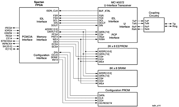
Three external memory devices are connected to the Spartan device.
A serial configuration PROM is used for device initialization. A 2Kx8
EEPROM is used to store the PCMCIA CIS data structure. An 8Kx8 SRAM provides
buffering for incoming and outgoing ISDN traffic.
Conclusion
Until digital modem ASSP manufacturers deliver more highly integrated solutions,
designers of these products will be faced with the task of interfacing a
variety of devices with incompatible interfaces. Xilinx high volume
FPGA and CPLD technologies provide system designers with cost effective
solutions that retain the traditional PLD time to market advantage.
References
MC145572
ISDN U-Interface Transceiver Manual, Motorola |
|