|
||
|
|
||
Xilinx : Support : techXclusives |
|||||||||||||||||||||||||||||||||
|
|
|||||||||||||||||||||||||||||||||
| techXclusives | |||||||||||||||||||||||||||||||||
|
|||||||||||||||||||||||||||||||||
|
|||||||||||||||||||||||||||||||||
|
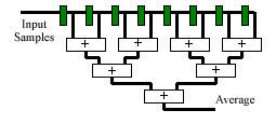
ENGINEER LEVEL: At this level, the applications of SRL16E require additional thought about alternative ways in which a problem can be solved. It is often possible to find a solution to a problem using shift register delay. Although HDL tools will automatically convert simple delays into SRL16E primitives, they are not able to change the structure of the design. As an engineer, you are able to discover these fresh approaches. The following two examples illustrate some realistic cases of such structures. Running Average The running average (or more accurately the running sum) of a set of samples has a smoothing effect associated with a type of low pass filter. In the example shown, the output is the sum of the last 8 samples held in a shift register. If we assume 16-bit input samples, then we have
In theory, assuming that the performance can be met by using the non-pipelined adder tree shown, the adders and registers can be mapped into the same CLBs, reducing this size to 32 CLBs. This may be considered to be an optimum solution; yet, using knowledge of SRL16E, we can go much further. The observation to make in this running average function is that a sample entering the shift register is contributing to the result for 8 clock cycles. Although a sample always contributes the same value to the result, it is doing so via different paths through the addition tree each cycle.
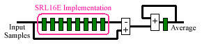
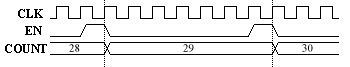
An alternative solution to this function is to use the fact that when a new sample is applied, it will contribute to the result for 8 cycles. This is achieved by adding the new sample to an accumulator that remembers the contribution that it made. After 8 clock cycles, we then subtract the delayed sample from the accumulator. Not only does this reduce the adder tree to a simple subtractor and accumulator, but it also forms the shift register into a simple delay line which is easily absorbed into SRL16E primitives. In this example, the 16-bit input samples still require 8 x 16 flip-flops for the shift register, but now fit into just 4 CLBs. The subtractor is 17-bits and the final accumulator is 19-bits (requiring a further 9 CLBs). The total size is 13 CLBs. In this example, a 60% size reduction was achieved over the most optimum mapping of the "obvious" technique. Clearly, as the length of the running average is increased, the savings are significantly greater. Pulse Generation and "Clock Division" Unless there are very special reasons to do so, the use of a single clock source (distributed via one of the global clock networks) should be used for all elements of a design. Clock enable pulses should then be used to enable subsections of the system to operate at a lower rate. In the diagram below, the enable pulses are used to enable a counter. Clearly, the pulse must occur at regular intervals and have a duration of one clock cycle.
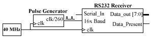
In this practical case study, we see an RS232 receiver module which will be used to receive serial data at 9600 bits per second (baud rate). Typical of most RS232 interfaces, this unit is provided with a timing reference which is 16 times the baud rate. In line with good design practice, this macro takes this reference as a clock enable pulse.
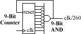
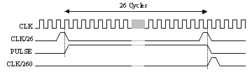
Pulses at 16 x 9600 baud are not an exact integer division of 40MHz. However a division by 260 is equivalent to 16 x 9615 which is more than adequate for RS232. This means that a pulse must be active for one cycle in every 260. A simple way to achieve this is with a 9-bit counter and AND gate detection of the count value 259 which is used to provide the pulse and synchronously reset the counter. This will require 6 "slices" of logic.
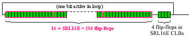
A counter can be viewed as a simple state machine. In this case, the 9 bits provide a possible 512 states of which the first 260 are actually used. The operation of the state machine is also very simple in that each state simply leads to the next (except when reaching the 259th state, which returns to zero). An equivalent "one-hot" state machine is one in which a different flip-flop is used to represent each state. Only the active state is at logic "1"; all others are logic "0." Since SRL can provide us with such a high number of flip-flops, this type of simple "one hot" state machine becomes very practical. It can be seen that 16 x SRL16E primitives and 4 flip-flops can provide the 260 states required.
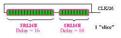
In this case, the SRL16E solution appears to be larger, but the simplicity of the technique is already clear. Although the "one-hot" state machine approach is very simple and ideal for small division factors, it is obvious that even with the efficiency of the SRL16E at providing flip-flops, there is a point at which the number of flip-flops required is too large compared with the doubling of states available with each additional bit of an encoded state machine counter. A solution to this is to "divide and conquer." The division by 260 can be broken into 2 stages. First, the clock will be divided by 26 to provide enable pulses to a second unit, which divides these enable pulses by 10.
The first stage simply requires a 26-state looped delay around which the single "hot" bit is clocked to produce an enable pulse. Clearly, the 26 flip-flops can be created in just two SRL16E primitives that are contained within a single "slice." (Note the high efficiency of the SRL16E implementation for this number of states; it is the equivalent of a 5-bit counter and decoder, requiring 3 "slices.")
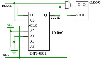
The second stage is a different style than the first, as it must divide the clock enable pulses from the first stage, rather than the clock directly. For this reason, the clock enable input to the SRL16E-based delay is driven.
Since this SRL16E is only enabled every 26 clock cycles, the output pulse is also active high for 26 clock cycles. To generate a single cycle clock enable pulse, this long pulse is gated with the input enable. The available flip-flop is used to ensure high performance, as such an enable pulse may have a high fan-out.
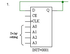
Forcing the "Hot" State The key to these pulse generators is the recycling of the "hot" state. It is therefore vital that the "hot" state is present in the delay loop at the start of operation. There are two ways in which this can be achieved:
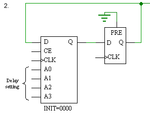
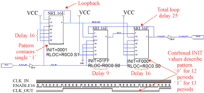
The most obvious method is to set the hexadecimal INIT value on the SRL16E look-up table. If necessary, the position of the "hot" bit can also be determined during start-up sequencing. It is important that the "hot" bit is declared to exist before the delay tapping point. (Note that in this example of INIT=0001, one loop of the delay is required before the first pulse is seen at the output.) Although the INIT parameter provides total control, this may not be easy to achieve via synthesis unless component instantiation is used. In this case, the default INIT=0000 can be used and the "hot" bit injected using the associated flip-flop. This flip-flop can be initialised with logic "1" by declaring (or inferring) an asynchronous preset. Obviously, the delay formed in the SRL16E is now one less. The flip-flop has the advantages of increasing the maximum delay available by one and improving the clock-to-output performance of the pulse generator. Pattern Generation Since the SRL16E can be pre-initialised with any INIT value, it can be used to produce a repeatable pattern. In this example, a clock signal is generated that is 400 times less than the input clock. In this case, the object is to produce a waveform which is close to square at the output. The solution is a divided by 16 stage which enables a divide by 25 stage. Note how the INIT values set the pattern of the output waveform.
Very High Performance Clock Division In this example, it has been possible to implement all logic in one CLB. The use of RLOC parameters ensures that the logic is mapped in this way. Given that all logic in a single CLB shares a common clock, there are no clock skew issues between the elements; thus, the input clock does not need to be provided on the global clock resource. The close proximity of the elements also yields very high performance (in excess of 350MHz). Such a circuit may be useful in dividing a high speed clock before use of a global clock resource in order to minimise the power dissipation. In general, a single clock and enable pulse is preferable. State Machines We have seen that the simple clock division or pulse generator is a form of "one-hot" state machine. This technique can be expanded to form more complex state machines. The use of shift registers to delay control pulses can be a very effective implementation method that can actually be easier to design than you might think.
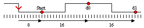
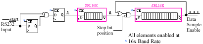
In this example, a simple RS232 receiver is considered. The serial data is provided at a rate of 9600 bits per second and has a single (active low) start bit and single (active high) stop bit. Although the serial data arrives asynchronously, the basic timing of the data is known. A reference time signal is provided at 16 x baud rate (see previous pulse generation example). The falling edge of the start bit is used to trigger a state machine which uses the timing reference to approximately locate the mid-position of each data bit.
It can be seen that the state machine must first count 8 timing reference periods to locate the mid-position of the "start bit," and then count every 16 timing reference periods to locate the midpoint of each data bit and the "stop bit." Once the "stop-bit" has been sampled, the state machine must return to the idle condition in which it locates the next falling edge of a "start bit."
Although this diagram does not show all the details required by the RS232 receiver state machine, it does illustrate the main functionality and the way in which the SRL16E primitives are so useful. In principle, we see a 24 state "one-hot" state machine with the 24 states represented by the flip-flops contained within the two SRL16E elements. In this case, all states are "cold" until a high pulse, formed when a high to low transition occurs at the RS232 input, is injected. The full implementation prevents multiple "hot" states from being generated due to following data transitions. The first SRL16E delays this pulse until the midpoint of the "start" bit, and then injects the "hot" state into the second SRL16E. This is then able to circulate every 16 baud rate-enable periods to identify the midpoint of each data bit. At the end of the data transmission, the "hot" state is prevented from re-entering the SRL16E, and the state machine returns to being "cold." A complete RS232 receiver for this specification can be made in 4 Virtex or Spartan II CLBs. Share your comments, questions and ideas with Ken Chapman and other interested designers at the "SRL16E" FORUM. |
|||||||||||||||||||||||||||||||||
| |
|||||||||||||||||||||||||||||||||
|
|||||
|
|
Troubleshoot | Hardware
| Software | Library
| Design | Education
| Services | | Home | Products | Support | Education | Purchase | Contact | Search | |