Copyright Michael Karbo and ELI Aps., Denmark, Europe.
Chapter 3. A data processor
The PC is a digital data processor. In practise this means that all analogue data (text, sound, pictures) gets translated into masses of 0s and 1s. These numbers (binary values) exist as tiny electrical charges in microscopic circuits, where a transistor can take on two states: charged or not charged. This is one picture of a bit, which you can say is either turned on or off.
There can be billions of these microscopic bits hidden inside a PC, and they are all managed using electronic circuits (EDP stands for electronic data processing). For example, the letter A (like all other characters) can be represented by a particular 8-digit bit pattern. For A, this 8-digit bit pattern is 01000001.
When you type an A on your keyboard, you create the digital data sequence, 01000001. To put it simply, the A exists as a pattern in eight transistors, where some are turned on (charged) and others are not. Together these 8 transistors make up one byte.
The same set of data can be stored in the video cards electronics, in RAM or even as a magnetic pattern on your hard disk:
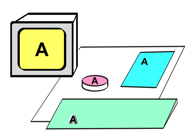 Fig. 14. The same data can be found on the
screen, on the hard disk and in RAM.
Fig. 14. The same data can be found on the
screen, on the hard disk and in RAM.
The set of data can also be transferred to a printer, if you want to print out your text. The printer electronically and mechanically translates the individual bits into analogue letters and numbers which are printed on the paper. In this way, there are billions of bytes constantly circulating in your PC, while ever it is switched on. But how are these 0s and 1s moved around, and which components are responsible?
The physical PC
The PC is made up of a central unit (also called a system unit) and some external devices. The central unit is a box (a cabinet), which contains most of the computers electronics (the internal devices). The external devices are connected to the central unit (shown below) using cables.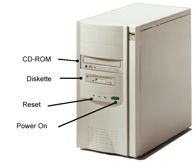 Fig. 15. The central unit contains the majority of a PCs electronics.
The cabinet shown in Fig. 15 is a minitower. In this cabinet, the motherboard is mounted vertically down one side. You can buy a taller cabinet of the same type. Its called a tower. If the cabinet is designed to be placed on a desk (under the monitor), it is called a desktop cabinet.
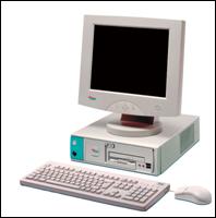
|
Fig. 16. A desktop cabinet. |
Fig.17 shows a list of most of the components of the PC. Some of them are internal, i.e., they are inside the cabinet. Other components are external, they are located outside the cabinet.
Read through the list and think about what the words refer to. Do you know all these devices?
|
Internal devices |
External devices |
|
|
Motherboard |
CPU, RAM, cache, ROM circuits containing the BIOS and startup programs. Chipsets (controllers). Ports, busses and slots. EIDE interface, USB, AGP, etc. |
Keyboard |
|
Drives |
Hard disk(s), diskette drive, CD-ROM, DVD, etc. |
|
|
Plug-in cards |
Graphics
card (video adapter), network card, SCSI controller. |
|
Fig. 17. The PCs components can be divided into internal and external groups.
Speed the more we get, the more we want
The PC processes data. It performs calculations and moves data between the various components. It all happens at our command, and we want it to happen fast.
It is interesting to note that current technological development is basically focusing exclusively on achieving faster data processing. The entire PC revolution over the last 20 years is actually just a sequence of ever increasing speed records in the area of data transfer. And there doesnt seem to be any upper limit to how much data transfer speed we need.
This continual speed optimisation is not just occurring in one place in the PC; its happening everywhere that data is moved.
The PC can be viewed as a series of more or less independent subsystems, which can each be developed to permit greater capacity and higher speed. We constantly need new standards, because of the new, faster, interfaces, busses, protocols (which we all work out together), delivering better performance.
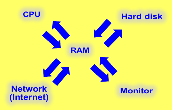 Fig. 18. Data transfer between all the components of the PC has to be fast.
Interfaces hold it all together
The PC is the sum of all these subsystems. At each boundary between one subsystem and another, we find an interface. That is, an electrical system which connects the two subsystems together and enables them to exchange data.
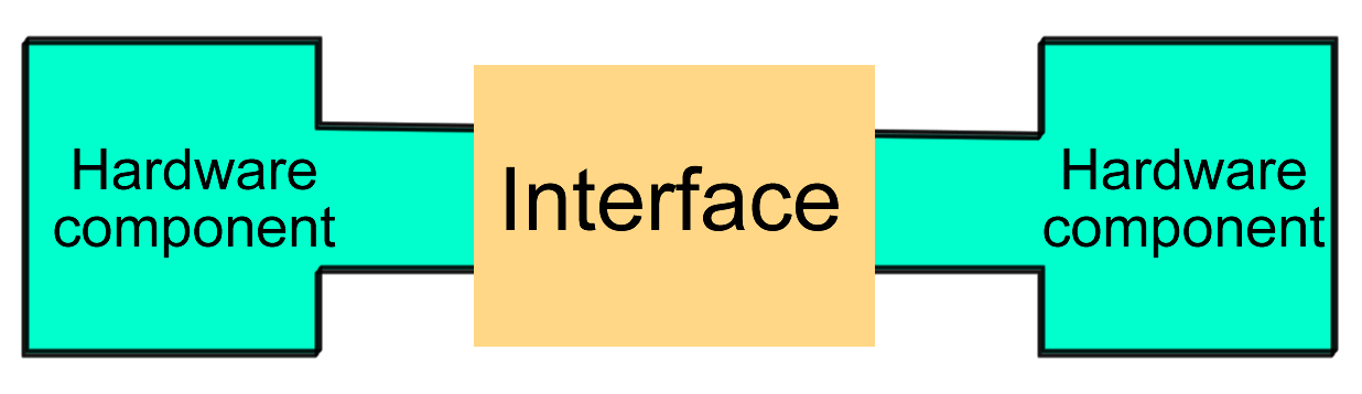 Fig. 19. The hardware components are
connected to each other via interfaces.
Fig. 19. The hardware components are
connected to each other via interfaces.
The concept of an interface is a little abstract, as it most accurately refers to a standard (a set of rules for the exchange of data). In practise, an interface can consist of, for example, two controllers (one at each end of the connection), a cable, and some software (protocols, etc.) contained in the controllers.
The controllers are small electronic circuits which control the movement of data to and from the device.
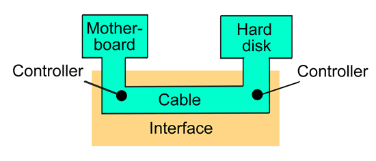
Fig. 20. An interface connects two hardware devices. An interface can consist of controllers with built-in software, cables, etc.
There are many interfaces in the PC, because there are many subsystems which have to be connected. Each interface is normally tailor-made for the job, and tuned to achieve maximum bandwidth (data transfer capacity) between the two components.
An example of an interface
Later in the guide I want to explore the EIDE interface in more detail, but I will use it here as a specific example of an interface. Keep your attention focused on the concept of an interface you may not understand all the details, that doesnt matter here.
If we want to connect a hard disk to a motherboard, this is achieved using an EIDE interface. If we look more closely at this interface, it can be divided into a series of subcomponents. The interface consists of both hardware and logic: the most important being the two EIDE controllers. One is integrated into the hard disks electronics, and the other is integrated into the motherboard, where it forms part of the chipsets south bridge.
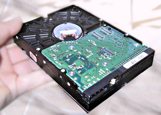
The advantage of this system is that the hard disk can be connected directly to the motherboard with a cable. But the cable still runs from one controller to the other.
The two controllers work according to a common standard, which is the ATA standard. This standard includes a set of protocols which are continually being developed in new versions. Lets say our specific hard disk can use the ATA/100 protocol. That means the controller on the motherboard has to also be compatible with ATA/100, and the cable as well. When all that is in place, we have a working ATA interface.
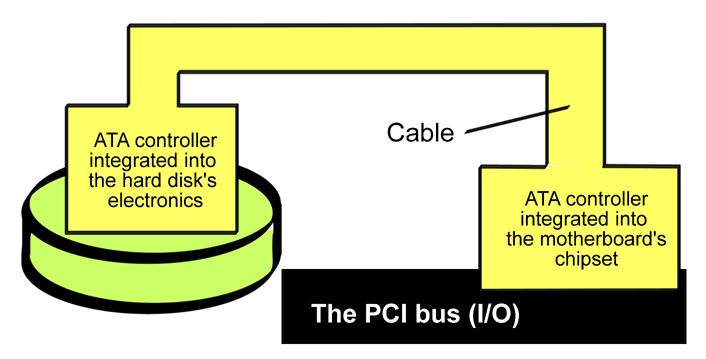 Fig. 22. A specific example of an
interface.
Fig. 22. A specific example of an
interface.