Copyright Michael Karbo and ELI Aps., Denmark, Europe.
Chapter 40. I/O buses using IRQs
I/O buses are designed to move data. Data is transferred from one I/O device to another, and from the I/O devices to the CPU and RAM. Lets delve a little deeper into the architecture which makes this possible.
At the physical level, the PCI bus consists of a number of parallel printed tracks on the motherboard. These tracks are used for:
Below we will take a look at the concepts of IRQ, DMA and I/O addresses.
Hardware interrupts
When you install a plug-in card in a slot, the card gets connected to the I/O bus. That means that data can run to and from the card. To manage the traffic on the I/O buses, a system is used, called IRQ. This stands for Interrupt Request.
Interrupts are basically one of the foundational principles of the PC architecture. There are two types: Software interrupts are used to call a large number of BIOS routines. Hardware interrupts are what we are now going to discuss, because these are what the I/O devices use.
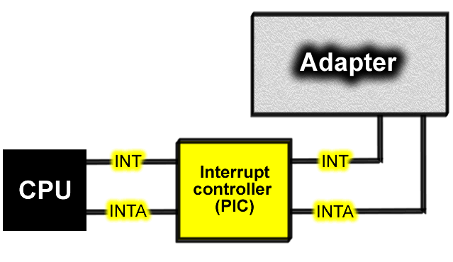
An interrupt signal is a doorbell used by the various PCI adapters and other devices. By setting an IRQ signal, they can ask to have the floor to be allowed to interrupt the CPU in the middle of its work. The device places a voltage across one of the conductors on the bus it sets an IRQ. When the CPU registers the signal, it knows that the device wants to fetch or deliver data, or has finished doing so.
The IRQ signals are managed by a PIC (Programmable Interrupt Controller), which is a controller device on the motherboard.
In the original PC design, the PIC was a loose controller chip (called Intel 8259). In modern motherboards the chipsets south bridge contains an equivalent, 8259-compatible, PIC function.
A practical example
The advantage of IRQs is that the CPU can keep working on other tasks while an adapter digests the data it has to look after. When the adapter has finished its work, it notifies the CPU using a new IRQ signal it rings the doorbell again.
Lets look at the keyboard as an example. Every time you press a key, an IRQ is sent from the keyboard controller to the CPU. First, the keyboard sends its data as a series of individual bits along the keyboard cable. The bits are received on the motherboard by the keyboard controller. On modern PCs this function is included in the Super I/O controller, but it used be on a separate 8042 chip. When the keyboard controller has collected one byte that is one character it sends an IRQ signal to the PIC (the IRQ controller).
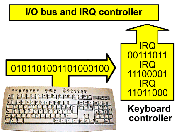
The signal requests permission from the CPU to send the character on. The PIC notifies the keyboard controller when the way is clear to the CPU, and then the byte is moved onto the I/O bus. At the physical level, an IRQ is a printed track on the bus. The printed track connects to all the PCI slots on the motherboard, so no matter which slot the adapter is installed in it has contact with the IRQ system.
8 or 15 IRQ lines
In the original PC architecture, an 8259 Programmable Interrupt Controller was used on the motherboard. It could handle 8 IRQ lines. This was later extended to two controllers with a total of 15 lines (one of the lines is used to connect the two PICs). That means there are 15 IRQs available to I/O devices. They are used for several tasks.
Certain system devices, such as the FPU (the number cruncher discussed earlier, and the system clock, each lay claim to one IRQ. Five of the IRQs are reserved for internal system devices like these. In Fig. 179 these are, for example, IRQ numbers 0, 8 and 13.
The remaining IRQs are available for I/O devices. You can also see in Fig. 179 that a number of IRQs are free. E.g. numbers 5, 7 and 10.
Each of the IRQs is a physical printed track that runs throughout the whole bus and hence the whole motherboard. The IRQs have different priorities, so that the CPU knows which IRQ should be given preference, if two signals are set at the same time.
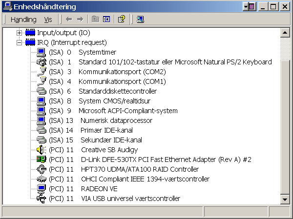
You can use the Windows Device Manager (or System Information) to see the way IRQs are distributed on your PC, as shown in Fig. 179. They should hopefully match.
Shared IRQs a typical PC solution
One of the big innovations in the PCI bus is that it allows shared IRQs. Two adapters can actually share an IRQ. In my PC there are no less than six devices sharing IRQ 11, and it works faultlessly.
The invention of shared IRQs is a good example of the evolutionary development of the PC architecture. The basic fault lies with the thin and undersized IRQ system; there are only 15 doorbells available in the system, and that is far too few.
It would be logical to extend the system to, for example, 256 doorbells. But that is not possible for compatibility reasons. The IRQ system is located at a very deep level in the PC architecture, and it would require complete reprogramming of both the CPU instructions and the operating systems if one changed it. And the PC would no longer be able to run, for example, old DOS programs.
In order to maintain compatibility, a work-around solution is typically chosen. A stopgap solution you could say but one which works. A doorman is employed at each doorbell. He checks who is ringing the doorbell which device is using the IRQ. And voila, using shared IRQs, the system works again!
How it was in the old days
Before the PCI bus came along we were stuck with the ISA bus, which was very limited by the small number of IRQs. It didnt take much before you were short of free IRQs if you needed several adapters in your PC. Sound cards used to especially play up. Sound cards are quite complex pieces of equipment, incorporating several functions. The old ISA based Sound Blaster cards usually claimed two IRQs and nothing less than two DMA channels as well. A card like that could be very difficult to install.
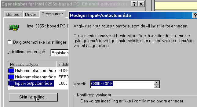
An ISA network card, might be configured by the manufacturer to work with IRQ 9, 10, 11 or 12, for example. One of the values (e.g. IRQ 11) was chosen as the standard factory setting (as the default value). When the customer installed the new network card, it would try, at startup, to go on the bus as IRQ 11. If there was no other device using IRQ 11 already, the card would probably work fine. But if IRQ 11 had been claimed by another card, there would be problems the two devices had a conflict. Often the PC wouldnt even start, and the air was thick with panic.
The solution was, for example, to change an IRQ jumper on the physical network card, and then try again. We are fortunately completely spared from that kind of mess with the newer PCs. The PCI bus checks itself which adapters are using shared IRQs, and the system functions quite automatically and problem free.
View the shared IRQs
Look a bit more closely at Fig. 179. The first thing to note is that it relates to an older motherboard, which also has an ISA bus. That is apparent by the fact that (ISA) is written in front of a number of the IRQs. Dont be too concerned about that, because the ISA bus is not actually used for anything nor are the IDE controllers, although you could get that impression from IRQ 14 and 15.
The following devices have been listed as located on the PCI bus, and they all use IRQ 11.
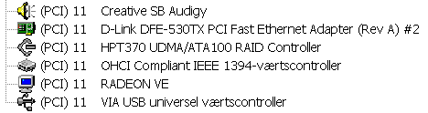
These devices are:
|
Device |
Description |
|
Creative SB Audigy |
Sound card |
|
D-Link Ethernet |
Network controller (network card) |
|
HPT 370 |
A RAID controller, built into the motherboard. |
|
IEEE1394 |
FireWire controller, built into the sound card. |
|
Radeon VE |
Video card (which is on the AGP bus). |
|
VIA USB |
USB host controller, built into the south bridge. |
Figure 180. Six logical devices which share the same IRQ.
DMA and bus mastering
DMA stands for Direct Memory Access, and is a system on the motherboard which permits an adapter to transfer its data to RAM without drawing on the PCs data processing power. Its actually the CPU which controls every event on the bus. With DMA, this intelligence has been put out in the DMA controller on the motherboard.
This special controller chip (Intel 8237, often integrated into the modern south bridge) is allowed to move data to and from RAM, via the I/O bus. And this happens without the CPU being burdened with the work.
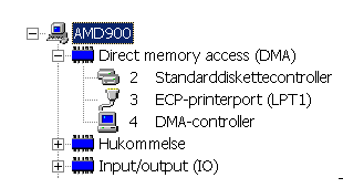
The motherboard has a number of DMA channels, each assigned a number. They are used by the ISA devices, which can each lay claim to one of the DMA channels. The floppy drive, for example, uses DMA:
There are no direct DMA channels on the PCI bus. Instead, bus mastering is used. It is a very similar system, where special controller functions permit adapters to take control of the bus. The adapters can then deliver their data directly to RAM, in a way which burdens the CPU as little as possible. It doesnt have to monitor the transaction the bus master looks after that.
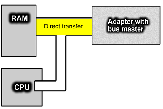
The goal is that the PC can multitask that is, handle several tasks at the same time. The hard disk can deliver data to RAM in a steady stream, while the CPU does other work at the same time. The bus mastering system works well with ATA devices, which work closely with RAM.
Though in this area, the SCSI controller is much more developed than the ATA controller. In practise, SCSI disks can operate almost independently of the CPU. SCSI interfaces are therefore still used to control hard disks in high-end servers and workstations.
Memory-mapped I/O
All devices, adapters, ports, etc. each have their own address. It is also called an I/O port number. The I/O address is necessary for the CPU (or RAM) to be able to fetch and send data to and from the device. The way this takes place inside the PC is called memory mapping of I/O devices.
Im not exactly sure how much practical benefit is derived from understanding this system. But it is part of the whole story, so Ill give you a quick overview. When you want to send data to your network card, it takes place through one or more I/O ports. These ports are located in RAM thats actually the whole idea.
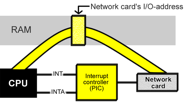
Thus when you want to send data to your network card, you send it to a particular area in the RAM. And the network card is ready to fetch its data from the same place, as soon as it gets the signal from the interrupt controller.
The PC can address (access) every byte in the RAM storage. And this addressing is exploited in the I/O ports. Every adapter is allocated a specific RAM address. That is, a small portion of RAM is linked to the I/O device. From then on, all data exchange to and from the device passes through this mailbox.
All I/O devices have their own mailbox number a port address. Since the PC is fundamentally a 16-bit computer, there are a total of 2 to the 16 (216 = 65,536) possible port addresses. They are specified using hexadecimal numbers, from 0000h up to FFFFh. Here are some examples of I/O addresses, as seen using the Windows Device Manager.
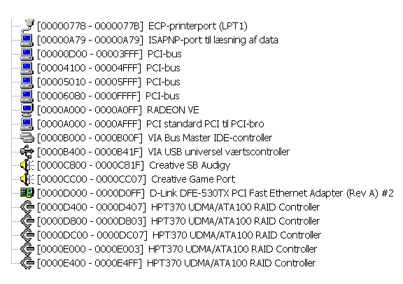
The table of I/O addresses takes up the bottom 64 KB of the PCs working storage ( from 0000h to FFFFh). The I/O addresses fall inside that special first megabyte of RAM which you might like to read about in the guide Do it yourself DOS. The individual I/O addresses can have varying lengths of up to 64 bytes.
We can see here that the system of I/O addresses was designed right back in around 1980, and is still being used. It is fortunately very rare that one, as a user, has to set up port addresses. Certain network cards support user-defined I/O addresses, but you would have to be very unlucky to encounter a conflict in this area.