A few years ago, graduates from our department raised concerns that they had never seen the inside of a computer nor had they installed an operating system such as Windows or Linux. This has changed, and much of the change has occurred in this class, CSCI 2150. This lab is the first of ten or eleven that introduce the student to the basics of PC installation, maintenance, and troubleshooting.
For many students in computer science, PC hardware and operating system installation is trivial. Either through requirements at their job, a desperate need to repair a home PC, or a passionate computer hobby, a number of people have learned to upgrade, maintain, and troubleshoot computers. If you are in this group, then this and many of the other labs based on the PC will seem trivial. The key is to make sure that everyone has achieved a certain level of competency when it comes to the systems they will be working with in future CSCI course and in their careers. If you feel that the repair and configuration of PCs is a trivial exercise, be sure to help those in the lab who are new to the concepts.
So as a CSCI student, what do you need to learn about the PC? Since each of you will be using the computer in different ways once you graduate, no one can really say. The way this class looks at it is that you should be able to make any of the upgrades or repairs commonly needed on a desktop machine. This includes troubleshooting problems, swapping defective parts, improving the computer's resources such as memory or drive capacities, or repairing or upgrading software including the operating system.
The first topic to tackle is to understand the configuration of the computer's hardware. Improper configuration can lead to problems such as boot failure or inaccessible resources. This lab provides a step-by-step procedure to introduce you to the system configuration.
If you miss the day we do this lab in class or if you would like to do the lab over again, you are more than welcome to come in during open lab hours to repeat the lab on your own.
Since this lab involves coming in contact with the internal circuitry of the computer, we need to talk about static electricity. It is not a question of whether static electricity will damage components, it always does. Sometimes, it may take a day or two or even a month for the damage to appear, but eventually the computer will begin to have random failures and then finally the damaged component will fail. A major goal of opening a computer case up for upgrade or repair is to not have to open it up again later for an additional repair.
You cannot predict when static electricity will occur. Yes, static electricity is worse when conditions are dry, but do not depend on that. Simply standing up or using cellophane tape could create enough charge to damage some electronics. That small spark jumping from the back of your hand to your hard drive can turn the drive into a door stop...a $60 door stop.
To avoid damaging components with static electricity, always, always, always touch a metal part of the computer's case or some other large piece of metal to ground yourself before coming close to any exposed electronic components.
The lab is also equipped with wrist straps that you can wear to safely ground yourself without restricting your movement. There are two parts to a wrist strap: an elastic wrist band and a coiled wire. Simply attach the alligator clip at the end of the coiled wire to the computer's chassis and attach the end of the wire with the snap to the snap on the wrist band. As long as the user is wearing this wrist band properly, he or she is statically discharged.
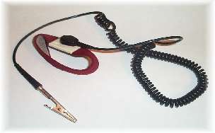
Anti-Static Wrist Strap
Improved mobility is only one benefit of the wrist strap. Each wrist strap contains a fuse that acts as a protection to the user in case the metal clip touches a high voltage source. Instead of shocking the user, the fuse blows and disconnects the user from the wire. Unfortunately, once this fuse blows, the wrist strap is no good and must be discarded. It is good practice to check the fuse in each wrist strap on a regular basis. This is done with an Ohmmeter, a device which checks to see if there is an electrical connection between two points.
If you or your lab partner are found not following anti-static procedures during any portion of a lab where electronics are exposed, you will automatically forfeit 10% (one letter grade) of your lab quiz grade.
This lab will introduce you to the operation of the computer's BIOS and the configuration of the computer's hardware. During the lab, you will:
You will be using some of the procedures shown in this lab in future labs, so it is important to understand them now.
First, let's look at the motherboard. We will begin by removing the cover.
The design of the Dell computers in our lab facilitates the quick removal of the components. Because of the wear these systems receive from constant disassembly and reassembly, removal of some components may have become more difficult with time, but you shouldn't have to force anything. Our lab PCs are tower machines that have been laid on their sides for easier access to the components. All of the instructions here assume that the machine is already on its side.
 In
the past, the power supplies needed to be removed in order to gain access
to the motherboard. In the GX260's that we are using now, the power supply
is small enough that this is unnecessary. If, however, you should need to
remove one for replacement, simply remove the two screws holding the supply
in the case, press the green tab where the supply rests on the case, and slip
the supply up and out. This is shown in the figure to the right. (Source:
Dell Documentation -- Higher Education, "Dell™
OptiPlex™ GX240 Service Manual")
In
the past, the power supplies needed to be removed in order to gain access
to the motherboard. In the GX260's that we are using now, the power supply
is small enough that this is unnecessary. If, however, you should need to
remove one for replacement, simply remove the two screws holding the supply
in the case, press the green tab where the supply rests on the case, and slip
the supply up and out. This is shown in the figure to the right. (Source:
Dell Documentation -- Higher Education, "Dell™
OptiPlex™ GX240 Service Manual")
In the old days, the majority of a computer's configuration, everything from the amount of memory installed to the number of serial ports, was configured with a device known as a jumper. Now everything is configured using the boot configuration screen which we will discuss in the next section. There is still one thing that we need to configure with a jumper.
A jumper, the blue block in the figure below, is used to straddle two pins on a circuit board to create a "short circuit" or electrical connection. The outside of the jumper is plastic, but a metal strip inside of the plastic is what connects the two pins.

These electrical connections between certain pins can be used to configure some of the most basic settings of the motherboard. In earlier generations of motherboards for example, if the processor was changed, the motherboard must alter the clock frequency that drives that processor. There were jumpers on the motherboard to do that.
The only jumper we need to be concerned with is a jumper that disables the BIOS password, the password that is required to configure the PC. If the user forgets the password used to configure the PC, then the configuration will never be able to be altered again. This jumper allows the password to be reset or disabled.
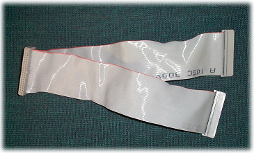
Looking down on the top of your motherboard (the dark green board that is mounted to the bottom of the case you've just opened), you should a bundle of colored wires going into a plug toward the front of the board near the power supply. Between this bundle of wires and the edge of the board, you should see a small jumper, typically black or green.
Next, we want to examine the hardware that is set up for your particular PC. The reason we will be doing this is to verify the system settings when we power up the machine.
Now you should have enough information about the computer to verify that it was configured properly in the system setup.
Note, your opportunity to successfully perform step 16 depends on you being able to quickly respond to your system prompt after power up. Therefore, read steps 15 and 16 before you do proceed.
After steps 15 and 16, the computer should respond by placing the message "Entering Setup" in the upper right corner of the screen.
After a moment, the first page of the system setup screen will be displayed. This is where we will be verifying the hardware configuration we examined in steps 7, 8, 9, and 10 in addition to examining how the system has been configured. The image below represents the setup screen. Note that the actual screen needs to be scrolled to show all of the options.
                           Dell - OptiPlex GX260
+--------------------------------------------------------------------------+
| Intel  Pentium  4 Processor: 2.00 MHz   | BIOS Version: A08              |
| LEVEL 2 Cache: 512 KB Integrated        | Service Tag : GRL8Q11          |
+--------------------------------------------------------------------------+
============================================================================
| System Time ......................................... 16:30:57           |
| System Date ......................................... Mon Sep 04, 2006   |
|                                                                          |
| Diskette Drive A: ................................... 3.5 inch, 1.44 MB  |

|                                                                          |
| Primary Drive 0 ..................................... Hard Drive         |
| Primary Drive 1 ..................................... OFF                |
| Secondary Drive 0 ................................... CD-ROM Reader      |
| Secondary Drive 1 ................................... OFF                |
|                                                                          |
| Boot Sequence ....................................... <ENTER>            |
|                                                                          |
| Memory Information .................................. <ENTER>            |
| CPU Information ..................................... <ENTER>            |
|                                                                          |
| Integrated Devices .................................. <ENTER>            |
| PCI IRQ Assignment .................................. <ENTER>            |
| IRQ Reservations .................................... <ENTER>            |
| Power Management .................................... <ENTER>            |
| System Security ..................................... <ENTER>            |
|                                                                          |
| Keyboard NumLock .................................... On                 |
| Report Keyboard Errors .............................. Report             |
|                                                                          |
| Auto Power On ....................................... Disabled           |
| Remote Wake Up ...................................... Off                |
| Fast Boot ........................................... Off                |
| IDE Hard Drive Acoustics Mode ....................... Bypass             |
|                                                                          |
| System Event Log .................................... <ENTER>            |
|                                                                          |
| Asset Tag ...........................................                    |
============================================================================
On the setup screen you should see configuration items such as:
At the bottom of the setup screen, you should see a menu of commands to use to modify the configurable items, to move the cursor, etc. For example, SPACE, +, or - will change the value of the currently highlighted field.
x 1. Diskette Drive x 2. IDE CD-ROM Device x 3. Hard-Disk Drive C: |
Now, we need to reboot the machines.
If your computer does not reboot, examine the possible reasons in the next section of this document.
Due to the number of components it takes to run a PC, there are a number of reasons why it might not come up. There is no substitute for experience. Once you've put a bunch of computer systems together, you'll know what to look for. In the absence of experience, however, there are a couple of things you can check first.
In an effort to make sure that your computer is capable of using the latest technology and to ensure its stable operation, we need to verify that the most basic code that the computer uses is the most up-to-date. The main component behind accessing the devices on a computer is called the Basic Input Output System (BIOS)
As will be explained in the lab on operating system installation, the BIOS is necessary to give the processor the rudimentary code in order to bring up the computer. It performs simple functions like testing the hardware (including memory), initializing hardware such as USB or printer ports, and creating the basic interface to storage devices such as the hard drives.
To put it in plain English, the operating system that is stored on the hard drive is completely useless unless the processor knows how to communicate with the hard drive in the first place. The operating system cannot handle the hard drive interface because the processor needs this interface before it can get anything from the hard drive, namely the operating system. This becomes a "which came first, the chicken or the egg?" problem.
Therefore, the next step in this lab is to verify that the latest BIOS has been loaded on your computer.
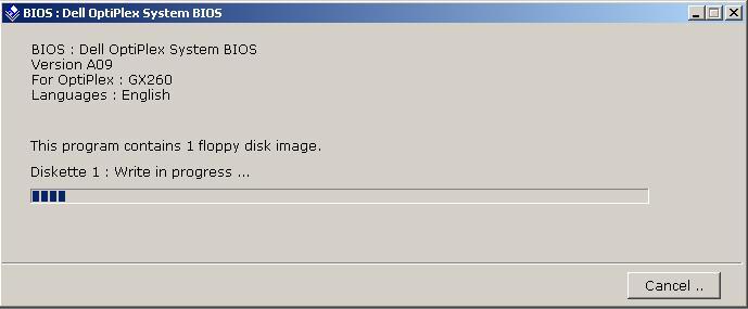
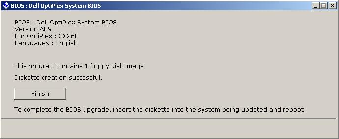
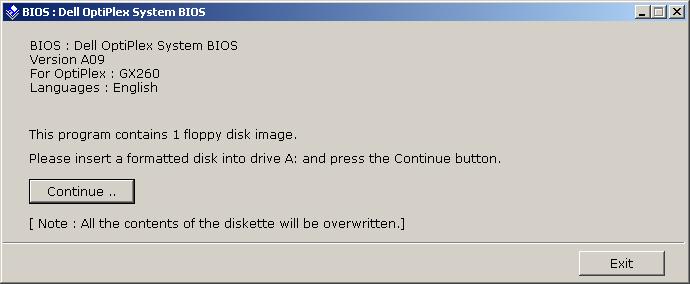
The latest BIOS for your computer should be available from the manufacturer's web site. In the case of the computers in the lab, the new BIOS's were downloaded in the form of an executable file from the Dell web site. In the lab, you should have access to a number of floppies containing this file, BR89214.exe. You may also download it to your home PC before class. This is not the BIOS, rather it is a program that will create a floppy diskette that then updates your BIOS.
Using this file and the following process, you should be able to update the BIOS on the Dell machines in the lab. Note that you will need to leave the CSCI lab's hard drive in the machine in order to complete this part of the lab.
NOTE: This procedure requires one blank, formatted 3.5-inch floppy disk; label the disk BIOS.
Dell gives the following standard warning about installing a new BIOS: "NOTICE: Changing the system BIOS may result in unintended side affects, such as incompatibility of the new BIOS with installed hardware. If problems arise after a BIOS change, it may be necessary to return the system to the original version of the BIOS." This procedure has been tried on all of the machines in the lab without any ill effects.
Steps 30 through 35 create a bootable diskette from which you will boot the lab PCs. When you boot the Dell GX260 from this diskette, it will take you through the rest of the BIOS download. The remaining steps take you through that process. If you haven't set up your boot sequence as described in step 24, do that now.
This step in the process is critical. Do not allow the PC to lose power until the process is complete. Losing power may corrupt the BIOS making the PC "unbootable".
The computer should restart and boot from the floppy disk. Now we will continue with the instructions for flashing a new BIOS.
Starting MS-DOS...

GX260A09.EXE

Loading...

Verifying system configurations.
Checking ROM file...
ROM file CRC-32 is correct.
Press any key to continue.
About to replace Dell System OptiPlex GX260 BIOS.
Press 'Y' to replace "A08" BIOS with "A09" BIOS.
The boot block code is different in the new flash.
The boot block will be flashed if you choose to continue.

A power loss during this process may cause the boot ROM to be corrupted.

Press 'C' to continue anyway.
Erasing Flash........... 100%
Programming Flash....... 100%
Comparing Flash......... 100%

Done! -- Press any key to reboot.
If the process went correctly, the computer should reboot with the new of the BIOS installed. Watch the boot screen which indicate the new BIOS version to verify this. Shutdown the computer and turn off the monitor to complete the lab.
Developed by David Tarnoff for students in CSCI 2150 at ETSU