
Virtually every PC manufactured today uses an Integrated Drive Electronics (IDE) interface to pass information back and forth between the motherboard and the higher volume storage devices such as hard drives, CDROMs, and tape drives. The term IDE describes the standard by which these devices are designed so as to facilitate the communication between them and the motherboard. IDE describes a set of rules such as the timing, electrical interface, and commands that will be used to transmit data.
Some of you may have noticed when you purchased your hard drives for this class that the interface was described as ATA. This is the original name given to the IDE interface owing to its origin in the IBM AT computer. ATA refers to AT Attachment. IDE interfaces are rarely if ever used to connect to external devices.
Standards such as IDE are vital to the way PCs are built and upgraded today. If a component of a computer is based on a well-defined and published standard, than any manufacturer wishing to create the same component could use the standard and the new part could be seamlessly swapped for the old. This is especially important for hard drives as they are a common upgrade.
The IDE interface devides the responsibilities of the hardware quite clearly between the IDE interface card (which is typically incorporated into the motherboard) and the hard drive controller (which is built into the hard drive itself). Back in the ol' days, the physical hard drive contained very little electronics. There was cable that ran from the drive to a small circuit board that plugged into the motherboard. The small circuit board contained all of the electronics necessary for the processor to store or retrieve data to the hard drive. This arrangement caused a number of problems including but not limited to:
By moving the responsibilities of physically accessing the platters from the motherboard to a controller card built into the hard drive, a more generic interface could be developed for data transfer. The generic interface that resulted is the IDE interface. The term Integrated Drive Electronics actually comes from the fact that the electronics for interfacing to the device are integrated into the drive itself.
Most of the motherboards you encounter will have one or two 40-pin IDE host adaptors built in. The image below shows two IDE host adaptors side-by-side on a motherboard, one labeled IDE1 and other labeled IDE2. IDE1 is the primary interface.
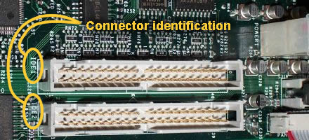
Each interface can handle up to two devices, so a motherboard with two IDE host adaptors can handle up to four drives.
As with all things computer related, advances in technology have allowed the devices we use to improve over time. The definition of IDE has expanded to allow for some of these changes. A brief description of each of these changes is presented below.
All of these standards maintain backwards compatibility, i.e., older drives can be used with the newer interfaces and newer drives can be used on older interfaces.
As was shown in the motherboard lab, the data connection for an IDE interface typically is integrated into the motherboard. In addition, there are usually two independent interfaces, IDE1 and IDE2, sometimes refered to as the primary and secondary. Each interface (i.e., connector) can support up to two drives. This allows a motherboard to control up to four IDE devices.
To connect a hard drive, we need to understand the purpose of each of the connectors on the back of the hard drive. If you pick up your drive, you should see an arrangement that looks something like the figure below.
First, the connection for the IDE interface is a 40-pin connector on the back of the hard drive. The pins are spaced 0.1" apart and are in two rows of twenty. Typically, (but you should verify this before you connect the drive) pin 1 is located nearest the connector for the power. If you remember from the motherboard lab, the ribbon cable used to connect the hard drive to the motherboard has a single red wire indicating "pin 1". The power connector also has a red wire. These red wires should be next to each other when connected to a standard hard drive.
Since each IDE interface allows for up to two drives on a single cable, you will need to be able to configure the drives so that one is the master drive and one is the slave drive. The master controls the interface and only allows the slave drive to communicate when the master is finished transferring its own data. In order for a slave drive to pass any data to the motherboard, it must first ask for permission from the master.
 There are a couple of ways to do this, each of which typically requires a physical
modification of the settings on the hard drive itself. Configuring a device
as a primary or secondary drive is usually done with a small plastic clip called
a jumper. A jumper, the blue block in the figure to
the right, is used to straddle two pins on a circuit board to create a "short
circuit" or electrical connection that the hard drive controller can detect.
The outside of the jumper is plastic, but a metal strip inside of the plastic
is what connects the two pins.
There are a couple of ways to do this, each of which typically requires a physical
modification of the settings on the hard drive itself. Configuring a device
as a primary or secondary drive is usually done with a small plastic clip called
a jumper. A jumper, the blue block in the figure to
the right, is used to straddle two pins on a circuit board to create a "short
circuit" or electrical connection that the hard drive controller can detect.
The outside of the jumper is plastic, but a metal strip inside of the plastic
is what connects the two pins.
Not all hard drives use the same configuration of jumpers to set the master/slave settings; the documentation that came with your drive or the information printed to the label affixed to the hard drive will outline the specifics for your drive. The most common way, however, will be described here.
Examining the back of your hard drive should reveal six pins situated between the 40-pin IDE connector and the 4-pin power connector. These pins are usually labeled MA, SL, and CS corresponding to master, slave, and cable select respectively. Placing a jumper so that is connects the two pins labeled MA makes the drive a master while placing a jumper across the pins SL make it a slave. If only one drive is on the IDE interface, it should be set to master or CS.
The other option is to use the CS setting. In this case, both drives on the cable must be set to use the CS option. It is the drive's position on the cable that determines whether it is the master or the slave. The master is connected to the connector that is at the end of the cable while the slave is connected to the connector in the middle. When the computer is powered up, a signal is sent down wire number 28 which is only connected to the middle connector. By not receiving this signal, the hard drive at the end understands that it is to take on the duties as master.
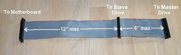
A quick note about the IDE cable. The standards that define the IDE interface also define the cable. The basic IDE cable cannot be longer than 18 inches. The middle connector cannot be further than 12 inches from the connector that goes to the motherboard and the last connecter cannot be further than 6 inches from the middle connector. These definitions are used to ensure the electrical characteristics of the connection from the motherboard to the hard drive. Longer cables will cause the data to attenuate or become corrupted by noise before reaching the device or motherboard. The image below shows how the connectors are arranged in this 2/3rd and 1/3rd configuration.
It might make little sense to place the master drive farther away from the processor. One might think that in the name of throughput, a closer drive would be desired. Actually, the problem is that if only one drive exists, and that drive is placed on the center connector, a dangling end would be created past the center connector that had no electrical connection. When current tried to flow down this end, then found no hard drive connected to it, the current would bounce back in what is referred to as a "reflection". This reflection would corrupt the next piece of highspeed data headed down the cable.
In addition, some cables have a plastic insert plugging the hole for pin 20. This was originally intended as a "key" to make sure that no one was able to plug the cable in backwards. Pin 20 on the hard drive (which has no assigned purpose) was often cut off to allow this cable to slide on only one way. Now most cables have a plastic key molded into the side of the connector.
The final connection to the hard drive provides power. This is a 4-pin connector with all four pins in a row and a plastic shield around the connector that is about 1" wide and is shaped like a trapezoidal. The shape of the plastic shield prevents the connector from being plugged in upside-down.
There have been a few modifications to the IDE cable over the past few years. First, as was mentioned earlier, with the advent of ATA-4, the IDE cables went to 80 conductors instead of 40. There are still 40 pins on the connectors, but between each of the "used" conductors, an additional conductor is inserted that is connected to ground (a voltage reference that carries no signal). This grounded conductor acts as a shield protecting neighboring devices from each other's signals. For example, in the figure below, the grounded conductors are shielding the signals radiating from conductor A thereby protecting conductor B from crosstalk.
Another change in IDE cables is the use of colored connectors. Newer IDE cables have a black connector, a gray connector, and a blue connector. The blue connector is to be connected to the motherboard, the gray goes to the slave (Drive 1), and the black goes to the master (Drive 0).
It is extremely easy to break or bend the pins that connect these devices together. Please take extreme care when connecting or disconnecting these devices. This includes pulling connectors off straight rather than at an angle or by prying one side up at a time. It also means that you shouldn't force connectors together. If your connector pins are bent, try gently straightening them before connecting your device to them. Failure to do this may result in damage to your drive or the lab computer.
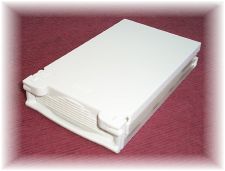
Each of the PCs in the lab has been outfitted with a bay to receive a carrier that contains your hard drive. You will be assigned a carrier for your hard drive so that when you come in to do your labs for the rest of the semester, you will simply slide your carrier into the bay of one of the PCs and perform the lab. The image below is of one of the carriers.
The process of opening one of the carriers isn't too bad, it's just not obvious. The sequence to opening a carrier is shown in the set of figures below.
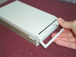 1.) Lift lever. |
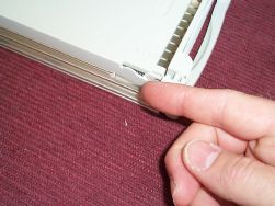 2.) Pull back clip on top left side. |
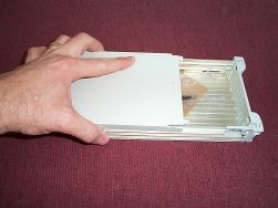 3.) Slide cover back. |
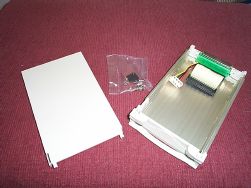 4.) Pull cover completely free. |
Examining the inside of the carrier reveals two connectors: one for the IDE interface and one for power. These need to be connected to your hard drive. I have two hints here.
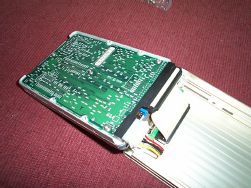 1.) Lay drive on its top before plugging in the connectors. |
 2.) Rotate drive into bay. |
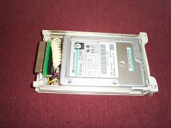
Now slid the top of the carrier back on being careful to align the groves in the top with the slots on the carrier body.
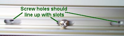
Lastly, we need to secure your drive in the carrier. If it is able to move inside the carrier, it may be damaged if it is allowed to bang back and forth. On the side of the carrier, you should see that the screw holes for the hard drive line up with the slots on the side of the carrier. Insert at least two of the screws that came with the carrier into these threaded holes to secure your hard drive.
Now your hard drive should be able to be inserted into the bay of one of the computers in the lab. You should be able to slide it into the bay oriented so the removable top of the carrier is on top. You should feel the back of the carrier come in contact with a connector at the back of the bay. Be sure to slide it all of the way onto the connector. The front edge of the handle should be flush with the front of the bay when the carrier is fully inserted.
Next to each computer there should be a barrel key with a black grip. This is used to lock the carrier into the bay. The drive will not work unless the carrier is locked in. Insert the key into the key slot on the right side of the bay. It should insert vertically. Turning the key so that it is horizontal will lock the bay into place.
Note that since your hard drive does not have an operating system at this time, the computer will not boot up successfully. We do, however, want to verify that the computer can see your hard drive.
Depending on the settings last used on the computer you are working with, you may have to do the following steps at the beginning of many of your remaining labs for this class.
After steps 1 and 2, the computer should respond with the following message:
"Entering Setup"
After a moment, the first page of the system setup screen will be displayed. This is where we will be verifying that the computer has found your hard drive.
Any hard drive loaded into the swappable hard drive bay of the computer should be set up as Primary Drive 0, i.e., the master drive on IDE1, of your machine. If your drive has not been identified in this field, a number of things may be causing this.
At this point, you should've successfully installed your hard drive. Unlock the hard drive carrier from its bay and place the key next to the computer for the next user.
Developed by David Tarnoff for students in CSCI 2150 at ETSU