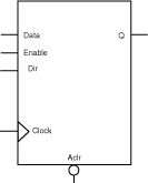

Parameterized word length
Standard or pipelined
Shift right, left, or both
Wrap around or feed bit
Fixed or programmable shift
SX, SX-A, eX, 500K, PA, Axcelerator, ProASIC3/E, Fusion
The Barrel Shifter can be generated for a fixed shift or range of shift, with feedbit shift or rotation in left, right, or both directions. The non-pipelined Barrel Shifter is designed to shift any number of positions at one time. For the pipelined version, it takes log2(MAXSHIFT) clock cycles for the shifted data to appear at the output.
The architecture is based on 2:1 multiplexors.
|
Port Description |
|
Port Name |
Size |
Type |
Req./Opt. |
Function |
|
Data |
WIDTH |
input |
Req. |
Register load input |
|
Aclr |
1 |
input |
Opt. |
Asynchronous register reset |
|
Dir |
1 |
input |
Opt |
For selecting Left or Right shift |
|
RFill |
1 |
input |
Opt |
For Right Feed Bit |
|
LFill |
1 |
input |
Opt |
For Left Feed Bit |
|
S0, S1… |
Log of Max. Shift |
input |
Opt |
For programmable, depends on Maximum shift |
|
Enable
|
1 |
input |
Opt. |
Synchronous Parallel load enable |
|
Clock |
1 |
input |
Req. |
Clock |
|
Q |
WIDTH |
output |
Req. |
Register output bus |
|
Parameter Description |
|
Parameter |
Value |
Function |
|
WIDTH |
2-99 (Pipelined) 2-63 (Standard) 2-99 (PA Fixed Programmable) 2-63 (PA Range Programmable) |
Word length of Data and Q |
|
MAXSHIFT |
1 Width-1 |
Maximum Shift length |
|
CLR_POLARITY |
0 1 2 |
Aclr can be active low, active high, or not used |
|
PROG |
Fixed or Range |
For a Fixed or Programmable shift |
|
FILL |
No, Yes |
Wrap around or Feed a bit |
|
DIRECTION |
Right Left Both |
Direction can be Right, Left, or Both |
|
EN_POLARITY |
0 1 2 |
Enable can be active low or active high |
|
CLK_EDGE |
RISE FALL |
Clock can be rising or falling |
|
Fan-in Control Parameters |
|
Parameter |
Value |
|
CLR_FANIN |
AUTO MANUAL |
|
CLR_VAL |
<val> [ default value for AUTO is 8, 1 for MANUAL] |
|
EN_FANIN |
AUTO MANUAL |
|
EN_VAL |
<val> [ default value for AUTO is 6, 1 for MANUAL] |
|
CLK_FANIN |
AUTO MANUAL |
|
CLK_VAL |
<val> [ default value for AUTO is 8, 1 for MANUAL] |
|
SEL0_FANIN |
AUTO MANUAL |
|
SEL0_VAL |
<val> [ default value for AUTO is 6, 1 for MANUAL] |
|
Implementation Parameters |
|
Parameter |
Value |
Description |
|
LPMTYPE |
LPM_DFF |
Register category |
|
LPM_HINT |
SHIFT, PIPE |
Standard or Pipelined |
|
Functional DescriptionA (Standard) |
|
Data |
Enable |
Clock |
Q |
|
M |
1 |
¦ |
Qn |
|
M |
0 |
¦ |
Mshifted |
|
A. Assume Aclr is active low, Enable is active high, Clock is rising. |
|
Functional DescriptionA (Pipelined) |
|
Data |
Aclr |
Enable |
Clock |
Q |
|
X |
0 |
X |
X |
0’s |
|
X |
1 |
0 |
X |
Qn = Mshifted - log2(MAXSHIFT) |
|
M |
1 |
1 |
¦ |
Qn+1 = Mshifted - log2(MAXSHIFT) + 1 |
|
A. Assume Aclr is active low, Enable is active high, Clock is rising. |