Parameterized word length
Up, Down, and Up/Down architectures
Asynchronous clear
Asynchronous preset (available only for Flash devices)
Synchronous counter load
Synchronous count enable
Terminal count flag (not available for Axcelerator)
Multiple gate-level implementations (area/speed tradeoffs)
Behavioral simulation model in VHDL and Verilog
ACT 2, ACT 3, 3200DX, MX, SX, SX-A, eX, 500K, PA, Axcelerator, ProASIC3/E, Fusion
Note: The counters that appear in SmartGen depend on the family you have specified in your workspace. To change your family, from the Options menu, choose Workspace Settings.
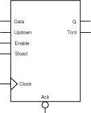
The SmartGen binary counters are general purpose UP, DOWN, or UP/DOWN (direction) counters.
When the count value equals 2width-1, the signal Tcnt (terminal count), if used, is asserted high.
The counters are WIDTH bits wide and have 2width states from “000…0” to “111…1”. The counters are clocked on the rising (RISE) or falling (FALL) edge of the clock signal Clock (CLK_EDGE).
The Clear signal (CLR_POLARITY), active low or high, provides an asynchronous reset of the counter to “000…0”. You may choose to not implement the reset function. If you do not use the Clear signal, Actel recommends that you use Sload to set the initial counter contents to a known value.
In the case of an Up/Down counter, the Updown signal controls whether the counter counts up (Updown = 1) or down (Updown = 0).
The counter could be loaded with Data. The Sload signal (LD_POLARITY), active high or low, provides a synchronous load operation with respect to the clock signal Clock. You can choose to not implement this function. If you do not use the Sload signal, Actel recommends that you use Clear to set the initial counter contents to a known value.
The SmartGen counters have a count enable signal Enable (EN_POLARITY). Enable can be active high or low. When Enable is not active, the counter is disabled and the internal state is unchanged.
|
Port Description |
|
Port Name |
Size |
Type |
Req./Opt. |
Function |
|
Data |
WIDTH |
input |
Opt. |
Counter load input |
|
Aclr |
1 |
input |
Opt. |
Asynchronous counter reset |
|
Enable |
1 |
input |
Req. |
Counter enable |
|
Sload |
1 |
input |
Opt. |
Synchronous counter load |
|
Clock |
1 |
input |
Req. |
Clock |
|
Updown |
1 |
input |
Opt. |
UP (Updown = 1), |
|
Q |
WIDTH |
output |
Req. |
Counter output bus |
|
Tcnt |
1 |
output |
Opt. |
Terminal count (active high) |
|
Parameter Description |
|
Parameter |
Value |
Function |
|
WIDTH |
2-32 |
Word length of Data and Q |
|
DIRECTION |
UP DOWN UPDOWN |
Counter direction |
|
CLR_POLARITY |
0 1 2 |
Aclr can be active low, active high, or not used |
|
EN_POLARITY |
0 1 |
Enable can be active low, or active high |
|
LD_POLARITY |
0 1 2 |
Sload can be active low, active high, or not used |
|
CLK_EDGE |
RISE FALL |
|
|
TCNT_POLARITY |
1 2 |
Tcnt can be active high or not used |
|
Fan-in Control Parameters |
|
Parameter |
Value |
|
CLR_FANIN |
AUTO MANUAL |
|
CLR_VAL |
<val> [default value for AUTO is 8, 1 for MANUAL] |
|
LD_FANIN |
AUTO MANUAL |
|
LD_VAL |
<val> [default value for AUTO is 6, 1 for MANUAL] |
|
CLK_FANIN |
AUTO MANUAL |
|
CLK_VAL |
<val> [default value for AUTO is 8, 1 for MANUAL] |
|
Implementation Parameters |
|
Parameter |
Value |
Description |
Family |
|
LPMTYPE |
LPM_COUNTER |
Counter category |
|
|
LPM_HINT |
LLCNT |
Prescaled model |
All |
|
|
TLACNT |
Register look ahead model |
All |
|
|
FBCNT |
Fast Balanced model |
SX, SX-A |
|
|
BCNT |
Balanced model |
All |
|
|
LECNT |
Fast Enable Balanced |
All |
|
|
COMPCNT |
Compact model |
All |
|
|
RIPPLE |
Ripple model |
All |
|
Functional Description A |
|
Data |
Aclr |
Enable |
Sload |
Clock |
Up down |
Qn+1 |
Tcnt n+1 |
|
X |
0 |
X |
X |
X |
X |
0’s |
0 |
|
X |
1 |
X |
X |
¦ |
X |
Qn |
Qn+1== 2width-1 |
|
X |
1 |
0 |
0 |
¦ |
X |
Qn |
Qn+1== 2width-1 |
|
m |
1 |
X |
1 |
¦ |
X |
m |
Qn+1== 2width-1 |
|
X |
1 |
1 |
0 |
¦ |
1 |
Qn + 1 |
Qn+1== 2width-1 |
|
X |
1 |
1 |
0 |
¦ |
0 |
Qn - 1 |
Qn+1== 2width-1 |
|
A. Assume Aclr is active low, Enable is active high, Sload is active high, Clock is rising, and Tcnt is active high |
This section decribes the implementation of the Pre-Scaled Counter, Register Look Ahead Counter, Fast Balanced Counter and the Balanced Counter.
Pre-Scaled Counter
The pre-scaled counter achieves absolute maximum count and count enable performance by sacrificing synchronous load performance. This counter registers the two least significant bits and uses them as an enable for the upper bits. Count performance is limited only by the delay in the lower two bits and the enable path for the upper bits. Because the upper bits are only updated (enabled) every fourth cycle, they can accommodate more delay (up to one-fourth the clock frequency).
There are two limitations related to the use of the pre-scaled counter. The first is in analyzing the actual performance of the counter. The second is correctly performing data load functions; these two limitations are related. Two parameters must be measured to overcome these two limitations. The first parameter that must be measured is the worst internal delay inside the counter. The second parameter is the worst delay from Q0/Q1 to any upper bit. The minimum count period is then defined by the greater value of these two parameters.
The load function is a slave of the maximum internal path delay in the pre-scaled counter. The load function must be held for as many clock periods as required to exceed the maximum internal delay; this ensures that all internal nodes are settled and that correct count operation can be performed. This requirement can be waived if you can guarantee that '0's will always be loaded in Q0 and Q1 (resulting in only a single load cycle).
The count path in pre-scaled counters without Sload or Enable functions only have a single logic level for ACT 2, ACT 3, 3200DX, MX SX, SX-A, and eX. All other combinations of pre-scaled counters have two logic levels in their count path. In these cases, given the two limitations mentioned previously related to the pre-scaled counter, use the Register Look Ahead or Fast Balanced counters.
Register Look Ahead Counter
This counter achieves the absolute maximum performance for the count, count enable, and synchronous load functions. The counter operates by registering intermediate count values providing “look-ahead” carry circuitry. As a result, this counter variation requires more flip-flops (sequential modules) than other counters.
Fast Balanced Counter
This counter is only available for the SX, SX-A, and eX families. It takes advantage of the architectural features of these families, including flip-flops with built-in enable and more powerful combinatorial cells. Using these two features, it is possible to build a very fast and compact binary counter without using “look-ahead” carry circuitry. This counter should be preferred over all the others available for this family.
Balanced Counter
This counter achieves high performance for both the count and enable functions using standard design approaches. Module count performance is sacrificed to maintain high speed. This counter is the result of the performance balance between the count/enable functions and the balance between the performance/cost in building this architecture. This counter should address most counter needs for the ACT 1, ACT 2, ACT 3, 3200DX, MX and MX families.
Pseudo Random Counter
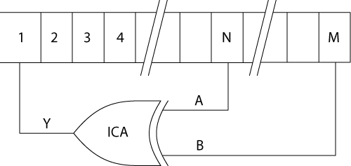
A Pseudo Random Counter is available in SmartGen using a Linear Feedback Shift Register (LFSR) architecture. The LFSR offers an efficient architecture for building very fast Pseudo Random Counters.

Generic Random Counter Architecture
The Pseudo Random core architecture core is a simple shift register chain that uses two taps (one logic level) for the following widths: 2-7, 9-11, 15, 17, 18, 20-23, 25, 28, 29, and 31. The SmartGen PRNG core uses five taps (three logic levels) for the following widths: 8, 12-14, 16, 19, 24, 26, 27, 30, and 32. The five-tap architecture operates slower than the two-tap implementation.
Fast Enable Counter
This compact counter is fully synchronous and has higher performance than the ripple counter. However, this counter should only be used in moderate performance applications, especially for large widths.
Ripple Counter
The ripple counter is an asynchronous counter where the Q of each bit feeds the clock of the next bit; performance is sacrificed to build this variation. However, the ripple counter uses the least amount of logic resources. This counter should only be used in very low-performance applications or for very small counters.
Because of the asynchronous nature of the count function, this counter does not have a synchronous load function.
Modulo Counter
As counter size increases, the amount and complexity of support logic also increases. LFSR base counters achieve high performance using very few logic resources. The Modulo Counter is designed to provide two logic levels independently of the chosen modulo value. The architecture borrows some look-ahead techniques previously used in the register look-ahead counter.
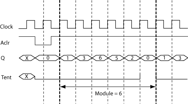
The example below is based on a modulo-6 counter with the following characteristics:
Active-HIGH clock edge
Active-LOW asynchronous clear
Active-HIGH synchronous clear
No Enable

Modulo Counter Behavior
