
Parameterized word lengths and constant values
Unsigned and signed (Two’s-Complement) data representation
Booth or array implementation
Optional pipelining
Behavioral simulation model in VHDL and Verilog
ACT 2, ACT 3, 3200DX, MX, SX, SX-A, eX, 500K, PA, Axcelerator, ProASIC3/E, Fusion
For information on the Fast Carry Chain associated with the Axcelerator device, click here.
|
Port Description |
|
Port Name |
Size |
Type |
Req/Opt |
Function |
|
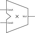
DataA |
WIDTHA |
Input |
Req. |
Input data |
|
DataB |
WIDTHB |
Input |
Req. |
Input data |
|
Clock |
1 |
Input |
Opt. |
Clock |
|
Mult |
WIDTHA+WIDTHB |
Output |
Opt. |
DataA*DataB |
|
Mult0 |
WIDTHA+WIDTHB |
Output |
Opt. |
Mult0 + Mult1 = DataA*DataB |
|
Mult1 |
WIDTHA+WIDTHB |
Output |
Opt. |
|
Parameter Description |
|
Parameter |
Family |
Value |
Function |
|
WIDTHA A |
500K, PA, Axcelerator |
2-64 |
Word length of DataA |
|
eX |
2-14 |
||
|
Other |
2-30 |
||
|
WIDTHB |
Same as WIDTHA |
Word length of DataB | |
|
REPRESENTATION |
|
UNSIGNED SIGNED |
Data representation |
|
FFTYPE B |
ALL except Flash |
REGULAR TMR CC |
FF Type Used (Default, Triple Voting, Combinatorial) |
|
CLK_EDGE |
|
RISE FALL |
Clock (if pipelined) |
A. For some of the multiplier variations there are small deviations from the limits mentioned to ensure that the multiplier fits in the largest device of the selected family.
B. TMR: Triple Module Redundancy. Choosing
this option makes SmartGen use TMR Flip-Flops which are used to avoid
Single Event Upsets (SEUs) for Rad-hard Designs. Choosing this option
causes the Sequential resource usage to be tripled in families where no
TMR is implemented in silicon.
CC: When combinatorial option is chosen for the Sequential Type, the FF
is implemented using two Combinatorial Cells instead of one Sequential
Cell. This is useful when no Sequential resources are available in the
designs.
This option is applicable only to the pipelined multipliers.
|
Functional Description |
|
DataA |
DataB |
Mult1 A |
|
m |
n |
m * n |
|
A. If pipelined, the sum is correct (available) after <latency> cycles. Latency is a function of WIDTHA and WIDTHB, or the number of pipelined stages mentioned specifically (e.g. 1 or 2 pipelines). |
|
Functional Description |
|
DataA |
DataB |
Mult0/1 A |
|
m |
n |
Mult1 + Mult2 = m * n |
|
A. Mult1<0> is always 0 |
|
Parameter Rules A |
|
Family |
Variation |
Parameter rules |
|
All |
All |
WIDTHA Š WIDTHB |
|
eX |
BOOTHMULT/P |
WIDTHA + WIDTHB <= 15 (signed) / 16 (unsigned) |
|
BOOTHMULTP |
For TMR restrictions for WIDTHA, WIDTHB | |
|
BOOTHMULT2 |
WIDTHA + WIDTHB <= 17 (signed) / 18 (unsigned) | |
|
SX/SX-A |
BOOTHMULT/P |
WIDTHA + WIDTHB <= 32 |
|
BOOTHMULT2 |
WIDTHA + WIDTHB <= 55 | |
|
Axcelerator |
ARRAYMULT |
WIDTHA + WIDTHB <= 128 |
|
PARRAYMULT |
WIDTHA + WIDTHB <= 128 | |
|
FC_BOOTHMULT1 |
WIDTHA + WIDTHB <= 106 | |
|
FC_BOOTHMULT1 |
WIDTHA + WIDTHB <= 106 | |
|
500K, PA |
All |
WIDTHA + WIDTHB <= 106 |
|
Other |
All |
WIDTHA + WIDTHB <= 32 |
|
A. These are the most important parameter rules; additional rules may apply. |
|
Implementation Parameters |
|
Parameter |
Value |
Description |
|
LPMTYPE |
LPM_MULT |
Multiplier category |
|
LPM_HINT |
BOOTHMULT |
Booth multiplier |
|
BOOTHMULT2 |
Booth multiplier without final Adder | |
|
BOOTHMULTP A |
Pipelined booth multiplier | |
|
LPMTYPE |
LPM_FC_MULT |
Fast Carry multiplier category (Axcelerator) B |
|
PARRAYMULT |
Fast Carry array multipliers in parallel. Each array multipliers consists of 1-bit Multipliers (MULT1); the rows of the array use fast carry chains, but there is regular routing between columns. | |
|
FCBOOTHMULT1 |
Booth-encoded Wallace-tree with Fast Carry final adder | |
|
FCBOOTHMULT2 |
Booth-encoded multiplier with n-bit Fast Carry adder tree |
|
A. Available for SX, SX-A, eX, 500K and PA (ProASIC) B. For information on multiplier area and performance please refer to the latest Actel application note available at http://www.actel.com |
In the Architecture Comparison tables below, WIDTHA = WIDTHB.
|
Axcelerator Multiplier Architecture Comparison: Speed |
|
Architecture/Speed |
1 (fastest) |
2 |
3 (slowest) |
|
Parallel-2 Array Multiplier |
width <= 8 bit |
8 bit < width <= 10 bit |
width > 10 bit |
|
FC Booth-1 |
8 bit < width <= 20 bit |
width <= 8 bit or width > 20 bit |
|
|
FC Booth-2 |
width > 20 bit |
10 bit < width <= 20 bit |
width <= 10 bit |
|
Axcelerator Multiplier Architecture Comparison:Area |
|
Architecture/Speed |
1 (smallest) |
2 |
3 (largest) |
|
Parallel-2 Array Multiplier |
always |
|
|
|
FC Booth-1 |
|
|
always |
|
FC Booth-2 |
|
always |
|
Click the Advanced button (available for PA, 500K, and Axcelerator devices) to specify pipeline stages. If you are using a PA or 500K device, you can insert (default setting) or omit the final Adder stage.
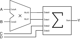
You can choose not to instantiate the final adder in the multiplier and add up the two buses Mult0 and Mult1 to the final result later in the design flow. This is often the most efficient implementation when a lot of partial results get summed up in a large summation network. The figure below shows an example for Y = (A x B) + C + D using the multiplier with two outputs in combination with the Array-Adder.

Efficient implementation using the two-output multiplier in combination with the Array-Adder
For ProASIC, ProASICPLUS, and Axcelerator devices you can specify the number of pipeline stages (1, 2, or 3). However, three pipeline stages increases performance only for high bitwidth. Click the Advanced button in the GUI to access pipelining.
|
Functional Description |
|
Pipeline Stages |
WidthB |
|
|
|
w/ Final Adder |
w/o Final Adder |
|
1 |
>= 2 |
>= 5 |
|
2 |
>= 5 |
>= 7 |
|
3 |
>= 7 |
Not applicable |
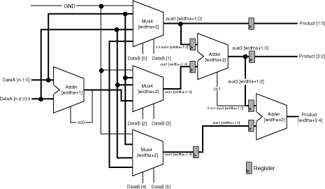
For ACT 2, ACT 3, 3200DX, MX, SX, SX-A, and eX the multiplier architecture does not allow you to select the latency of the pipelined multiplier or the number of logic levels between the pipeline stages. Registers are automatically inserted between the major components of the architecture, primarily the multiplexor and adder cores, as shown in the figure below.

Booth Multiplier Architecture (Pipeline)
The number of pipeline stages is a function of the width of the DataB input. The number of logic levels per pipeline stage is a function of the width of the DataA input. Therefore, the number of logic levels per pipeline stage is equal to the number of logic levels of the first adder (WIDTHA + 1) plus 1 for the 4 to 1 multiplexor, as shown in the figure above.
|
Pipeline Stages as a Function of WidthB |
|
WidthB Range |
Pipeline Stages |
|
2 |
0 |
|
3-4 |
1 |
|
5-8 |
2 |
|
9-16 |
3 |
|
Logic Levels per Pipeline Stage as a Function of WidthA |
|
WidthA Range |
Logic Levels |
|
2-5 |
3 |
|
6-17 |
4 |
|
18-29 |
5 |
For more information on the Fast Carry-Chain cores available with the Axcelerator family, please refer to Fast Carry Chains (Axcelerator only).