
Parameterized word length
Asynchronous clear
Synchronous parallel load
Behavioral simulation model in VHDL and Verilog
ACT 1, ACT 2, ACT 3, 3200DX, MX, SX, SX-A, eX, 500K, PA, Axcelerator, ProASIC3/E, Fusion
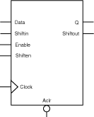
Shift registers have parallel-in/parallel-out (PIPO), parallel-in/serial-out (PISO), serial-in/parallel-out (SIPO) and serial-in/serial-out (SISO) architecture. The registers are WIDTH bits. They are clocked on the rising (RISE) or falling (FALL) edge of the clock signal (CLK_EDGE).
The Clear signal (CLR_POLARITY), active high or low, provides an asynchronous reset of the registers to “000…0”. You may choose to not implement the reset function.
Shift registers can be loaded with Data. The Enable signal (EN_POLARITY), active high or low, provides a synchronous load enable operation with respect to the clock signal Clock. You may choose to not implement this function. Shift registers are then implemented in a serial-in mode (SIPO or SISO).
Shift registers have a shift enable signal Shiften (SHEN_POLARITY) that can be active high or low. When Shiften is active, the register is shifted internally. The LSB is loaded with Shiftin.
In the current implementation, Enable has priority over Shiften.
|
Port Description |
|
Port Name |
Size |
Type |
Req/Opt |
Function |
|
Data |
WIDTH |
input |
Opt. |
Register load input data |
|
Shiftin |
1 |
Input |
Opt. |
Shift in signal |
|
Aclr |
1 |
input |
Opt. |
Asynchronous register reset |
|
Enable |
1 |
input |
Opt. |
Synchronous parallel load enable |
|
Shiften |
1 |
input |
Req. |
Synchronous register shift enable |
|
Clock |
1 |
input |
Req. |
Clock |
|
Q |
WIDTH |
output |
Opt. |
Register output bus |
|
Shiftout |
1 |
output |
Opt. |
Serial output |
|
Parameter Description |
|
Parameter |
Family |
Value |
Function |
|
WIDTH |
500K, PA |
2-512 |
Word length of Data and Q |
|
All other |
2-99 |
||
|
CLR_POLARITY |
All |
0 1 2 |
Aclr can be active low, active high, or not used |
|
EN_POLARITY |
All |
0 1 2 |
Enable can be active low or active high |
|
SHEN_POLARITY |
All |
0 1 |
Shiften can be active low, active high, or not used |
|
CLK_EDGE |
All |
RISE FALL |
Clock can be rising or falling |
|
Fan-in Control Parameters |
|
Parameter |
Value |
|
CLR_FANIN |
AUTO MANUAL |
|
CLR_VAL |
<val> [default value for AUTO is 8, 1 for MANUAL] |
|
EN_FANIN |
AUTO MANUAL |
|
EN_VAL |
<val> [default value for AUTO is 6, 1 for MANUAL] |
|
SHEN_FANIN |
AUTO MANUAL |
|
SHEN_VAL |
<val> [default value for AUTO is 6, 1 for MANUAL] |
|
CLK_FANIN |
AUTO MANUAL |
|
CLK_VAL |
<val> [default value for AUTO is 8, 1 for MANUAL] |
|
Implementation Parameters |
|
Parameter |
Value |
Description |
|
LPMTYPE |
LPM_DFF |
Register category |
|
LPM_HINT |
PIPOS |
Parallel-in/Parallel-out shift register |
|
PISO |
Parallel-in/Serial-out shift register | |
|
SIPO |
Serial-in/Parallel-out shift register | |
|
SISO |
Serial-in/Serial-out shift register |
|
Functional Description A |
|
Data |
Aclr |
Enable |
Shiften |
Clock |
Q B |
Shiftout B |
|
X |
0 |
X |
X |
X |
0 |
0 |
|
X |
1 |
X |
X |
Ø |
Qn |
Qn = [WIDTH-1] |
|
X |
1 |
0 |
0 |
¦ |
Qn |
Qn = [WIDTH-1] |
|
X |
1 |
0 |
1 |
¦ |
Qn[ WIDTH-2:0] && Shiftin |
Qn = [WIDTH-1] |
|
m |
1 |
1 |
X |
¦ |
Qn+1 = m |
Qn+1 = m[WIDTH-1] |
|
A. Aclr is active low, Enable is active high, Shiften is active high, Clock is rising. B. For the PISO and SISO implementations, Q is an internal register. C. For the PIPO and SIPO implementations, Shiftout is not present. |