Clock conditioning and PLL cores are available only for ProASIC3/E devices.
After you make all your selections, SmartGen generates a core with your configurations. However, there are a number of restrictions in the possible values for the input and output frequencies. They are:
Input to the clock conditioning core (CCC) must be between 1.5 and 350 MHz
Output from the CCC must be between 1.5 and 350 MHz
The reference input to the PLL core (fin/n) must be between 1.5 and 5.5 MHz. The PLL Core output must be between 24 and 350 (fin *m/n)
Your requested PLL values are not possible in all cases, because of the VCO input, output frequency limitations, available divider ranges and inter-dependencies between the multiple outputs. In such cases, SmartGen tries to generate a value that is as close as possible to the value you requested. The actual values that SmartGen can achieve are shown on the screen (in blue), next to where the requested values are specified. If you hit generate, the core is generated with the actual values rather than the specified values. The actual values are also included in the log file for future reference.
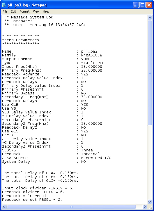
Here is a sample of the SmartGen log file containing all the information.
If more than one output is specified, SmartGen tries to find the multiplication and division factors such that the total error among all the outputs is the least.
SmartGen prints out the total delays of the selected outputs after feedback delay, feedback advance, system delay, and extra output delay are taken into consideration.
Total Delay on an Output = -feedback advance – de-skew system delay + feedback delay + extra output delay + intrinsic delay
The delay between the input of the PLL and a given output can be calculated by the following equation.
Total Delay = Intrinsic delay +/- feedback delay – mask delay + phase delay + output delay
Intrinsic delay is the total delay of all the muxes and divider elements in the path. This is a fixed value for a given connectivity in a configuration. This delay varies based on the mux selection, frequency values and phase-shifts. Changing the delay element values has no impact on the intrinsic delay.
Feedback delay can be both a positive and a negative delay based on how it is configured.
Mask delay is a fixed system delay to emulate the skew of the CCC, such that the output can be deskewed by selecting this delay.
Output delay is the programmable delay independently selectable for each output.
Phase delay is the shift caused in the output with respect to the input when the VCO output is shifted by one of the 4 possible values of 0, 90, 180 or 270 degrees. This is a function of both input and output frequencies.
The delay calculation is executed using the same values for SmartGen, the Simulation model and Timer such that, for typical, -2 parts under normal operating conditions, these numbers are identical. This enables you to fine-tune your delays by only adjusting the programmable output / feedback delays.