The Current, Temperature, and Voltage peripherals are all configured the same way. Also, the effects of averaging are the same for all peripherals in the Analog System Builder.
Minor variations, such as Maximum Voltage in the Voltage monitor, are explained in the help topic for that peripheral.
Signal name is the name of the signal as you want it to appear in the main Analog System Builder dialog box.
Digital filtering factor
Once the ADC finishes converting the Analog Signal to a digital value, it filters (averages) the resulting digital output. Digital filtering is a single pole low-pass filter built in soft gates; you can use it to improve the signal to noise ratio.
The filtered value is calculated using the following equation:
OUTn = OUTn_1 + (IN / S) – (OUTn_1/S)
Where S is the Digital filtering factor. If the Digital filtering factor is set to 1 it is ignored.
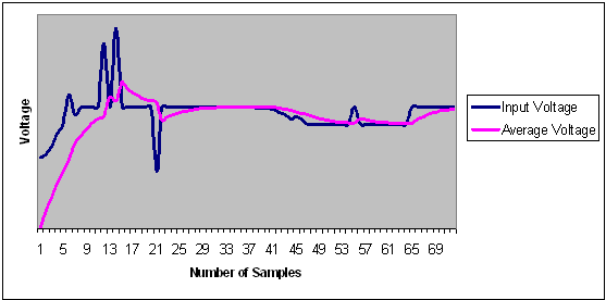
The system instantiates the logic required to perform averaging as soon as there is at least one channel in the system that requires averaging. There is no extra logic penalty for averaging the other channels of the system. The figure below shows the effect of averaging on a given signal.
Effect of Averaging on Voltage
Acquisition Time
The required settling/sampling time for this channel. It is the amount of time the Sample and Hold circuit in the ADC charges the capacitor with the input analog signal.
Comparison Flag Specification
Once the software calculates the average, you can run further processing on the result. Compare the result to a given threshold to determine whether it is above or below a given threshold, and decide under what conditions to assert the comparison flags.
Select a flag and click the Delete button to delete it.
Click the Add Flag button to add more flags to the system.
Flag Name - This is the name of the flag. This will appear as the output port name in the final output. It will be prefixed with the signal name with which it is associated, to group the input and outputs together.
Flag Type - You can choose to assert the flag when the signal is either under a given threshold or over a given threshold.
Threshold - Threshold value. The figure below shows the effect of the threshold on a given signal.
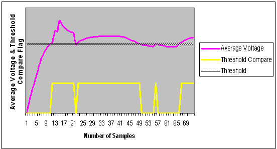
Threshold Comparison
Assert Samples - The number of consecutive samples on this channel that reach or pass the threshold for the flag to assert. This can be is a glitch removal feature. If it is set to 1, the final flag is identical to the comparison result.
For example, if your Assert Sample value is 3.0 V, the channel must surpass 3.0 V five times in a row on this channel for the flag to assert. If you your voltage values are less than 3.0 V, the flag will not assert. The figure below shows the effect of glitch removal on a given signal.
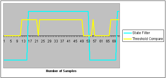
Glitch Removal
De-assert Samples - The number of consecutive samples of this channel that are not in above the threshold required for the flag to de-assert once it has been asserted. This is a glitch removal feature. If this value is set to 1, the final flag is identical to the comparison result.
For example, if your De-assert Sample value is 3.3 V, you must have 10 consecutive samples that do below 3.3 V in order for the flag to de-assert.