Designer tool
You can run Designer when your post-synthesis EDIF
netlist is ready. For
structural designs you can start Designer directly using your source files
as input.
Colors:
Green - Designer succeeded
in creating your back-annotated files and they are current.
Red - Designer failed.
See the
Libero log window for information.
White - Status undefined.
Run Designer
to generate your post-layout files; the Designer button will change to
green or red.
You can invoke Designer even if your netlist is out
of date. If
you wish, you can update your netlist manually (or with the Synthesis
tool) before you start Designer.
If your Designer outputs (back-annotated or programming/debugging
files) are out of date, re-run Designer to make them current.
Actel's Designer software is integrated with Libero
IDE. Use the Designer software to implement your design.
To implement your design:
Start
Designer. Right-click the top level module in the Design
Hierarchy and select Run Designer,
or click Designer in the Design
Flow window. Designer starts and loads your files from Libero.
Set up your device. From
the Tools menu, choose Device
Selection. In the Device Selection Wizard, select your device type,
device package, speed grade, voltage, and operating conditions. Make your
selections and click Next to complete
the steps
Compile
your design. In Designer, click Compile
in the design flow window. The log window displays the utilization
of the selected device. When compile has completed, the Compile box in
the Design Flow window turns green.
Designer's
User Tools. Once
you have successfully compiled your design, you can use Designer’s User's
tool to optimize your design. To start a tool, simply click it in the
flow tree. The tools include:
|
Tool |
Function |
Supported Families |
|
PinEditor |
Package level floorplanner and I/O attribute editor |
All |
|
ChipPlanner |
Logic viewer, placement and floorplanning tool |
Axcelerator,Flash |
|
ChipEditor |
Logic viewer and placement tool |
All |
|
NetlistViewer |
Design schematic viewer |
All |
|
SmartPower |
Power analysis tool |
Axcelerator, Flash |
|
Timer |
Static timing analysis and constraints editor |
All |
Layout
your design. Click Layout
in the Design Flow Window to place-and-route your design.
Back-Annotate
your design. Click Back-Annotate
in the Design Flow Window. Choose SDF
as CAE type and appropriate simulation language. Select Netlist in the
Export Additional Files area and Click OK.
If you are exporting files post-layout, Designer exports <top>_ba.vhd
and <top>_ba.sdf
to your Libero project. The “_ba” is added by Libero to identify these
for back-annotation purposes. <top> is the top root name. Pre-layout
exported files do not contain “_ba” and are exported simply as *.vhd and
*.sdf. The
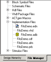
files are visible from the File Manager, under Implementation Files.
Generate
a programming file. Click Programming
File in the design flow tree if you wish to create a programming
file for your design. This step can be performed later after you are satisfied
with the back-annotated timing simulation.
Save
and Exit. From the File
menu, click Exit. Select Yes to
save the design before closing Designer. Designer saves all of the design
information in an *.adb
file. The <project>.adb
file is visible in Libero’s File Manger, in the Implementation Files folder.
To re-open this file at any time, simply double-click it. Files in the File Manager.
