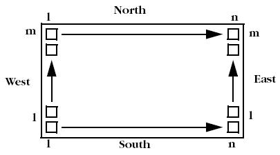
Generally, you are concerned with the mapping of signals (ports) to the pins of the selected package. However, you may want to control the allocation of signals to particular pads. This is accomplished by assigning ports to the pad location rather than to the package pin. Because all pads are pre-bonded to package pins, the effect is to assign ports to package pins, with the emphasis on pad location rather than package pin.
Pad location is described by the letters N (North), S (South), E (East) or W (West) followed by a space and a number. This location code determines the direction and offset of the pad with respect to the die.
The top edge of the viewer contains the North pads and the right edge contains the East pads. The number refers to the pad position along its edge. For example, N 48 corresponds to the 48th pad along the North edge of the die. The figure below shows the numbering system used for pad location.
