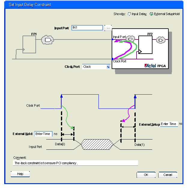
Use this dialog box to define the arrival time relative to a clock.
The following diagram shows the Input Delay view of the SDC.

The following diagram shows the External Setup/Hold view of the SDC.

You can see the current constraints setup either by Input Delay or External Setup/Hold. By default, the tool displays the Input Delay specific settings.
Specifies an input pin from the design to use as a clock source
Displays a Pin Selector dialog box. Use this dialog box to select any input pin in the design.
Specifies the clock reference to which the specified input delay is related. The drop-down list displays all possible Obvious Clocks in the design.
Specifies that both maximum and minimum delay values are equal.
Specifies the value of the input delay in nanoseconds for the longest path arriving at the specified input. This value is a real number of accuracy up to 3 decimal places.
Specifies the value of the input delay in nanoseconds for the shortest path arriving at the specified input. This value is a real number of accuracy up to 3 decimal places.
Specifies a real number of accuracy up to 3 decimal places
Specifies a real number of accuracy up to 3 decimal places