|
"8x12=96" and "12x8=96"...so what is Ken Chapman on about this
week?
Well I haven’t quite gone mad just yet, it’s just that I’m
thinking about those Xilinx Virtex and Spartan-II devices again and
how multipliers are constructed in the CLBs. I will prove to you
that "8x12" is not equal to "12x8", and hopefully in the process,
provide you with some details of how to get the most out of your
designs that contain multiplication.
To prove this, I need to bend the rules a little, and change my
definition of the maths! In my case I’m not going to consider the
numerical values of "8" and "12," but consider the multiplication of
an 8-bit value and 12-bit value.
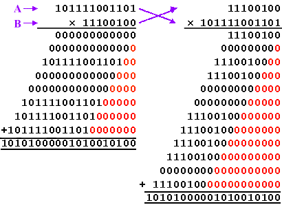
Here we see full binary (unsigned) multiplication of the values
3021 (BCD hexadecimal) and 228 (E4 hexadecimal).
The act of multiplication comes down to some very simple
procedures. I have labeled the two inputs "A" and "B". The
multiplication is performed by taking each bit of "B" in turn, and using it to multiply the whole
of input "A". Now in binary this is very simple. Since one bit can
only represent the value "0" or "1," then the result of this one-bit
multiplication can only be the value zero or "A".
It then requires that all these partial products are added
together to form the final product of multiplication. Of course, we
have to restore the original bit weighting associated with each bit
of "B", and this is achieved by the ever-increasing partial product
shifting to the left that is provided by the "0" padding on each line.
Regardless of which value is the multiplicand, and which is the
multiplier, the result is always 688788 (A8294 hexadecimal) and I’m
still losing the game!
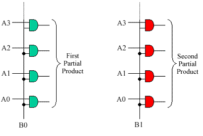
The one-it multiplication is logically very simple requiring only
sets of AND gates. These either allow the "A" value to be passed, or force the partial
product completely to zero.
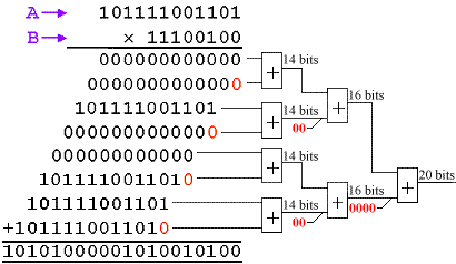
Then, we need to add all the partial products together with
appropriate bit weighting. If we have time (enough clock cycles), we
can adopt the classical "shift and add" technique based on an
accumulator, but in this case I am looking for a maximum performance
parallel multiplier. For this, I will need an "addition tree".
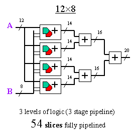
It can be seen that the bit weighting is restored throughout the
addition process. It is always easy to determine the number of bits
required at any stage, as each adder output is in itself a partial
product of the final result. As shown, the first adders provide the
products of the 12-bit input "A"
multiplied by 2 bits of "B", and hence
generate a 14-bit (12+2) product. The second stage adders require
16-bits to represent a 12-bit by 4-bit product. The final result is
then the full 20-bit product.
Obviously, the addition of zero bits does not require a real
addition process. However, if the adder is pipelined, then the least
significant bits to which zero is added will also require flip-flops
to balance the pipeline delay. These flip-flops occupy the same
space as a full adder (unless that wonderful SRL16E can combine
several stages together).
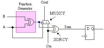
Since addition is such a key part of this multiplication process,
let’s review how a full adder is so cleverly achieved in Virtex and
Spartan-II. Each function generator (of which there are 4 in each
CLB arranged into 2 "slices") is complemented by a simple 2-input
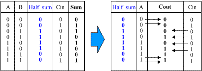
XOR gate called XORCY and a 2:1 multiplexer called MUXCY. From the
left-hand truth table for a full adder, it is clear that the sum in
the result of A xor B xor Cin.
In Virtex and Spartan-II, this function is broken into two parts
such that the Half_sum = A xor
B is generated first using the function generator, and then the
dedicated XORCY is used to form the full sum of Half_sum xor Cin. The clever bit can be
seen in the right-hand table. This shows how the Half-sum is used to control the MUXCY
multiplexer which generates the carry output. Notice how the Half_sum selects either the original carry
input or the "A" input.
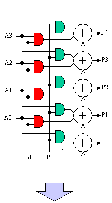
Whilst the latter stages of the addition tree are pure
add functions, look at the way in which the first two partial
products are formed and then applied to the first stage adder. This
means that in the majority of cases, the two adder inputs are each
driven by a 2-input AND gate. As these AND gates would each occupy a
function generator, a multiplier suddenly becomes very large in an
FPGA. In my case of a 12-bit by 8-bit multiplier it would require
12x8 = 96 function generators (48 slices) just to implement the AND
gates.
However, we can quickly see an optimisation. The AND
gate associated with one of the adder inputs can be absorbed into
the function generator forming the Half_sum for addition. This in itself reduces
the size of the 12-bit by 8-bit multiplier by 48 function generators
(24 slices).
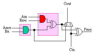
It would be nice to absorb the other AND gate into the
function generator, but the signal it produces is also required by
the MUXCY part of the addition function. So this would appear to be
the most we can achieve.
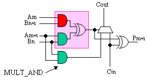
However, Virtex and Spartan-II does allow this second
AND gate to be absorbed. Next to each function generator is yet
another component called the MULT_AND. It has the effect of
re-creating the same input to the MUXCY, even though the desired
signal is now buried within the function generator.
So, back to the issue of "8x12" not being equal to
"12x8".
Since all the AND gates associated with multiplication
are essentially free in Virtex and Spartan-II, the structure of a
parallel multiplier is the same as that for an addition tree with
the first stage adders also performing the multiplication by two
bits of "B". As we break the "B" word into 2-bit sections, so the resulting
addition tree must reflect the number of bits in the "B" word.
------
--------------------------------------------------------------------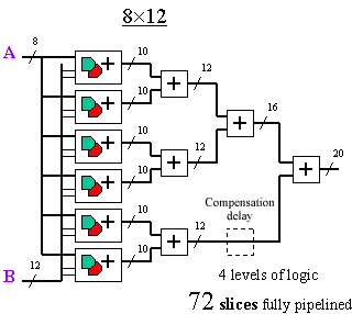
The fact that 8 is a power of 2 means that the "12x8"
breaks down nicely into 4 multiplier adders in the first stage;
hence, it leads to a symmetrical addition tree of 3 levels. In
contrast, the "8x12" is less elegant: the 6 multiplier adders of the
first stage do not sum easily, leading to more adders and 4 levels
of logic. For a fully pipelined multiplier, there is even the
requirement for delay compensation.
Admittedly, the multiplier adders and pure adders of
the "8x12" are generally a smaller number of bits than in the
"12x8"; but with Virtex and Spartan-II, this has a very minimal
impact on performance. In any case, both multipliers have the same
largest-size adder at the final stage. Combinatorial multiplier
performance will be set by the number of logic levels, and in this
case, the "12x8" will definitely win.
So, I have eventually proven that 8x12 is not
equal to 12x8 when it comes to the size and performance of
multipliers in Virtex and Spartan-II devices. Consider this as you
use full parallel multipliers in your designs.
The Variable Parallel Multiplier IP contained in the
Core Generator allows you to define the width of the "A" and "B" ports,
so do consider the impact this will have. The data sheet indicates
that latency is a function of the "B"
port; if you play with the GUI, you will see instant feedback that
for an 8x12 the latency is 4 cycles. For the 12x8, it is just 3
cycles. I suggest that this information is also used to determine
the number of levels of logic in combinatorial multipliers before
actually selecting the combinatorial option.
If you are an HDL user, try to understand how your
tool maps what you write to the structure. All synthesis tools
stating that they specifically target Virtex or Spartan-II devices
should be making full use of the MULT_AND gate, and hence producing
optimum area solutions. However, you may need to experiment to
discover the "A" and "B" port-mapping.

A more significant issue with HDL coding is
performance. Although the above VHDL example will generate a
multiplier, it will result in a combinatorial multiplier with a
single register at the output. To increase performance, the addition
stages really do need to be pipelined. This is where you may insert
a Xilinx IP Core.
Alternatively, your code could describe the internal
structure of the multiplier in more detail. Synthesis vendors have
also been looking at coding styles combined with "re-timing," which
can distribute lumped register delays following a multiplier back
into the addition stages. In this case, it is vital that you
understand the particular synthesis tools you use and that you fully
appreciate that...
“8x12 is not equal to 12x8”
Share your comments, questions and ideas with Ken Chapman and
other interested designers at the "8x12 Does NOT Equal 12x8" FORUM. | 
