|
(continued from page 1)
A More Optimum RGB2YPBPR Solution
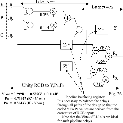
Figure 26 shows 2 multipliers, 2 adders, and 2 subtracters used to construct the Luma component (Y). This solution will be smaller than that of Figure 25, due to the need for 1 fewer multiplier at the expense of just two subtracters.

Coding PBPR to Give CBCR
So far, you have seen diagrams for RGB to Y PBPR.
PBPR are the ± 0.5V analogue colour-different outputs often found on the rear panels of broadcast studio equipment. The signals can also be sent as digital video components in both serial and parallel
form at Standard Definition (SD) and High Definition (HD), data rates, 27MHz and 74.25MHz respectively.
The quantization requirements for coding Y PBPR as Y CBCR are defined in Recommendation ITU-R BT.601-4 601, often referred to as Rec. 601.
Rec 601 is primarily concerned with broadcast quality imaging and outlines a quantization scheme that provides some “headroom” and “footroom” in the quantized values for Y CB and CR. It is worth noting
that Rec-601 originally proposed 8-bit values for digital component video, but it is now industry standard to use10-bits. Rec-601 reflects this modification by stating that all 10-bit values should be treated as an 8-bit exponent and 2-bit mantissa.
The values used in Rec-601 are given in 8-bit notation, and this has been maintained below so as not to confuse the reader by introducing 10-bit values.
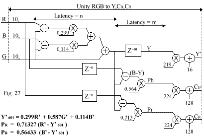
The full excursion of the Luma is quantized across 220 levels (0->219), and footroom in the signals is provided by offsetting the minimum Luma signal to value 16. Hence, Y601 is achieved by multiplying the colour converted
Y output by 219 and adding 16 to the result. Headroom in the Y601 signal is achieved by the scaling multiplier and offset, which ensure that a maximum excursion of Y gives a Y601 value of 235. This leaves
values (236->254)** as headroom.
The full excursion of each colour difference channel is quantized across 225 levels (0->224) by multiplying the 2’s compliment PBPR signals by 224 and applying an offset of +128. This causes the 2’s
compliment CBCR outputs to swing across the digital range -112 and +112, leaving values (0->15) and (113 ->127) as footroom and headroom in the Rec-601-compliant digital output.
** Levels 0 and 255 are used exclusively for synchronization.
An RGB to YCBCR Solution

ARTICLE SUMMARY
This section has provided some background material into the principles of colour and how it is coded and transmitted in different coordinate systems that define "colour space."
Hopefully, the terms (RGB), (Y B-Y R-Y) (Y,PB, PR) and (YCBCR) should now have some meaning when you hear the term "colour space converters" in the
future.
This article has only covered the conversion from RGB to digital component colour space. The reciprocal conversion is similar in its use of multipliers to scale data and adders/subtracters to add and remove offsets given by Rec-601.
FURTHER INFORMATION:
Having derived a block diagram of what needs to be built, the following Power Point presentations move on to the Matlab/Simulink and System Generator domain to explore how the theory can be modeled:
|
Section A
|
Section B
|
Section C
|
|
|
|
|
|

