
A Current Sensing Tutorial--Part 1: Fundamentals
4 comments
After reading this series of articles on current sensing, you will have a solid grasp of the fundamentals of current sensing, devices used for current sensing, how to calculate the accuracy of a solution, and guidelines for printed circuit board (PCB) layout and troubleshooting. This article discusses the fundamentals of current sensing, including direct versus indirect sensing, input common-mode voltage, high versus low-side sensing, directionality, and output requirements.
Why is current sensing important?
Knowing the amount of current being delivered to a load can be useful in a wide variety of applications. For example, in low-power consumer products the supply current can be monitored to understand the systemís impact on battery life. The load current also can be used to make safety-critical decisions in over-current protection circuits. In motor control, knowing the magnitude and direction of the current can tell you the speed and direction of the motor. Finally, test fixtures can be developed that monitor all supply currents to gain an understanding of system subcomponent performance. Each of the aforementioned applications has different design requirements with respect to common-mode voltage, directionality, and accuracy.
Types of current sensing
There are two types of current sensing: direct and indirect. Indirect current sensing is based on Ampereís and Faradayís laws. By placing a coil (for instance Rogowski coil) around a current-carrying conductor, a voltage is induced across the coil that is proportional to the current. This allows for a non-invasive measurement where the sensing circuitry is not electrically connected to the monitored system. Since there is no direct connection between the sensing circuitry and the system, the system is inherently isolated. Indirect current sensing typically is used for load currents in the 100A-1000A range. This type of sensing, however, requires relatively expensive sensors and is not conducive to sensing currents on a PCB.
Direct current sensing is based on Ohmís law. By placing a shunt resistor in series with the system load, a voltage is generated across the shunt resistor that is proportional to the system load current. The voltage across the shunt can be measured by differential amplifiers such as current shunt monitors (CSMs), operational amplifiers (op amps), difference amplifiers (DAs), or instrumentation amplifiers (IAs). This method is an invasive measurement of the current since the shunt resistor and sensing circuitry are electrically connected to the monitored system. Therefore, direct sensing typically is used when galvanic isolation is not required. The shunt resistor also dissipates power, which may not be desirable. Direct current sensing typically is implemented for load currents <100A. The remainder of this particular article series will focus on direct current sensing.
Input common-mode voltage
Input common-mode voltage is the most important specification when selecting a direct current sensing solution. It is defined as the average voltage present at the input terminals of the amplifier. Figure 1 depicts the definition of input common-mode voltage [1].
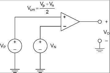
Figure 1: Definition of input common-mode voltage.
This specification is important because it limits our choice of differential amplifiers. For example, op amps and IAs require an input common-mode voltage within their power supplies. Difference amplifiers and CSMs, however, typically can accommodate input common-mode voltages in excess of their power supplies. This is useful in applications where the amplifier senses the shunt voltage in the presence of a large common-mode voltage and must interface with a low-voltage analog-to-digital converter (ADC). In such a scenario the amplifier and ADC can be powered with the same supply voltage regardless of the systemís common-mode voltage.
High-side versus low-side current sensing
When monitoring load current the designer can choose to place the sense resistor either between the supply voltage (Vbus) and load, or between the load and ground. The former is called high-side sensing whereas the latter is called low-side sensing.
Low-side sensing is desirable because the common-mode voltage is near ground, which allows for the use of single-supply, rail-to-rail input/output op amps. The drawbacks to low-side sensing are disturbances to the system loadís ground potential and the inability to detect load shorts. Figure 2 depicts a typical low-side sensing scenario.
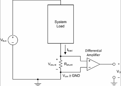
Figure 2: Low-side current sensing.
High-side sensing is desirable in that it directly monitors the current delivered by the supply, which allows for the detection of load shorts. The challenge is that the amplifierís input common-mode voltage range must include the loadís supply voltage, or Vbus. This requirement frequently necessitates the use of DAs or dedicated CSMs, which allow for common-mode voltages outside their voltage supply range. Figure 3 depicts a typical high-side sensing scenario.
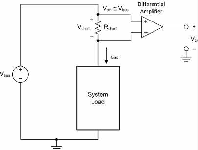
Figure 3: High-side current sensing.
Directionality
Depending on the application, the supply current may flow either in one direction (unidirectional) or both directions (bidirectional). Unidirectional designs are straightforward in that the output voltage of the amplifier does not need to distinguish direction. If a bidirectional design is required, however, how can the designer distinguish direction of current flow? Bidirectional solutions have an input for a reference, or pedestal voltage. The output of the device is then referenced to this known voltage. Output voltages above the known reference voltage are in one direction while output voltages below the known reference voltage are in the opposite direction. Figure 4 depicts the concept of current directionality.
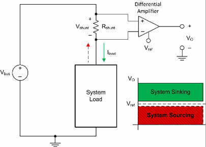
Figure 4: Directionality.
Current Sensing Tutorial
Output
The output of a current sensing solution can be in the form of a current, voltage, or digital word. Dedicated CSMs can have any of the aforementioned outputs while op amps, DAs, and IAs have a voltage output.
Current output CSMs typically require an external gain-setting resistor (RL) as shown by the INA138/168 diagram in Figure 5. This allows for flexibility in choosing the gain of the device. Also, if the design requires driving a large capacitive load, a properly compensated external op amp can buffer the output of the CSM. However, since the gain of the device depends on the external resistor, the internal resistors must be trimmed to an absolute value, which can increase cost.
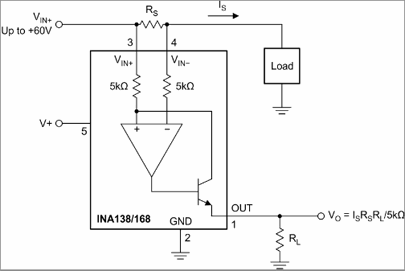
Figure 5: Current output CSM.
Voltage output CSMs integrate the gain-setting resistor and output buffer as shown by the INA193-8 diagram in Figure 6. This only requires ratio-metric trimming which is less costly than absolute trimming. The drawback is that the devices have predetermined gains (for instance 20V/V, 50V/V, 100V/V) and the designer does not have access to the feedback path of the buffer amplifier to compensate for large capacitive loads.
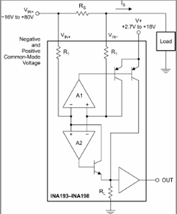
Figure 6: Voltage output CSM.
Digital output CSMs have integrated programmable-gain amplifiers (PGAs) and ADCs and report the shunt voltage as a digital word via a serial communication protocol such as I2C or SPI, as shown by the INA219 block diagram in Figure 7. While this can be highly desirable for ease-of-use, the full-scale differential input must be restricted to a range of values. Therefore, care must be taken when selecting the value of the shunt resistor.
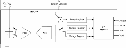
Figure 7: Digital output CSM.
Summary
In summary, this article has provided a fundamental understanding of current sensing solutions. An understanding of common-mode voltage, high versus low side sensing, directionality, and output requirements has been gained. The next article in this series will take a closer look at the four differential amplifiers commonly used in direct current sensing solutions. These include the op amp, DA, IA, and CSM.
References
[1] Tobey, Graeme, Huelsman, ďOperational Amplifiers: Design and ApplicationsĒ, McGraw-Hill, 1971.
For answers to current sensing applications questions please visit TIís Precision Amplifiers forum in the E2E community.
The complete series
- A Current Sensing Tutorial--Part 1: Fundamentals
- A Current Sensing TutorialóPart II: Devices
- A Current Sensing Tutorial--Part III: Accuracy
- A Current Sensing TutorialóPart IV: Layout and Troubleshooting Guidelines
About the Authors
Peter Semig is an Applications Engineer in the Precision Linear group at TI where he supports difference amplifiers, instrumentation amplifiers, and current shunt monitors. Peter received his BSEE and MSEE from Michigan State University, East Lansing, Michigan. If you have questions about this article, contact Peter at ti_petersemig@list.ti.com.
Collin Wells is an applications engineer in the Precision Linear group at TI where he supports industrial products and applications. Collin received his BSEE from the University of Texas, Dallas.
