Verilog HDL
2007/06/18 22:22
http://blog.naver.com/PostPrint.nhn?blogId=babojay&logNo=40038879588#
Chapter 5.
Gete-Level Modeling
지금까지 Verilog의 기본적인 것들에 대해 알아보았다. 이제 실제 하드웨어의 모델링을 살펴보자. 하드웨어 기술(H/W description)에 네 개의 추상화 단계 중 Gate level modeing에 대해 먼저 살펴본다. 디지털회로에 대한 기본지식이 있다면 gate level이 이해하고 설계하기에 가장 직관적이라고 생각된다. 이보다 더 낮고 기초가 되는 switch level modeling이 있지만, 구조와 동작이 복잡하고 직관적이지 못하기 때문에 나중에 다루기로 한다. 더구나 실제 설계현장에서 switch level로 모델링 하는 예는 그리 많지 않기 때문이다.
*Objectives
- Verilog에서 지원하는 Logic Gate
Primitives.
- and/or , buf/not 게이트의 진리표와 심볼과 instantiation의 이해
-
Logic diagram으로 부터 Verilog 로 기술하는 방법의 이해
- rise, fall, turn-off delay의
이해
- min, max, typ delay의 이해
5.1 Gate Types
- Primitives : 기본적으로 제공되는 미리 정의 되어 있는 logic gate modules
5.1.1 And/Or Gate
- 한개의 output, 다수의 input.
- port list의 맨 처음에 오는 터미널은
output이다.
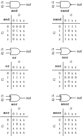
그림 5.1 기본적인 gate symbol과 진리표
Ex)
wire OUT, IN1,
IN2, IN3;
// 기본적인 gate
instantiation
and a1(OUT, IN1, IN2);
nand na1(OUT, IN1, IN2);
or or1(OUT, IN1,
IN2);
nor nor1(OUT, IN1, IN2);
xor
x1(OUT, IN1, IN2);
xnor nx1(OUT, IN1, IN2);
// 2개 이상의
입력
nand na1_3inp(OUT, IN1, IN2, IN3);
// 인스턴스 이름의
생략
and (OUT, IN1, IN2);
* 별도의 정의 없이 사용가능하며, 리스트의 순서에 의해 연결이 이루어진다.
(out, i1, i2, i3,...)
** 2개 이상의 입력을 원할 경우 원하는 입력을
그냥 적어준다.
*** 인스턴스 이름이 없어도 된다.
5.1.2 Buf/Not Gates
- 한개의 input, 다수의 output.
- port list의 맨 마지막에 오는 터미널이
input이다.
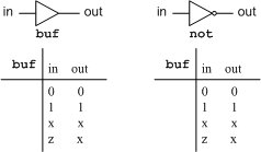
그림 5.2 기본적인 gate symbol과 진리표
Ex)
// basic gate
instantiation
buf b1(OUT1, IN);
not
n1(OUT1, IN);
// 2개 이상의
output
buf b1_2out(OUT1, OUT2, IN);
// 인스턴스 이름의
생략
not (OUT1, IN);
■ bufif/notif
- 제어신호(control signal)을 갖고 출력을 제어하는 buf/not gate이다.
- 제어신호는 정상출력을 출력하거나
z(High impedance)를 갖게 하는 기능을
한다.
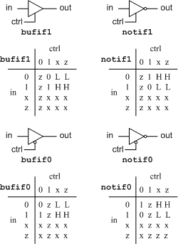
그림 5.3 bufif/notif의 symbol과 진리표
* bufif0/notif0는 control 신호가 negative active동작을 하게 된다.
Ex)
//
bufif
bufif1 b1(out, in, ctrl);
bufif0 b0(out, in, ctrl);
//
notif
notif1 n1(out, in, ctrl);
notif0 n0(out, in, ctrl);
5.1.3 Examples
■ Gate-level multiplexer(4-to-1)

그림 5.4 4-to-1 Multiplexer
이를 Logic Diagram으로 표현하면 다음과 같다.
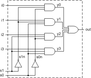
그림 5.5 Logic diagram for 4-to-1 MUX
Ex)
// Module
4-to-1 MUX
module mux4_to_1(out, i0, i1, i2, i3, s1,
s0);
output
out;
// Port declaration
input i0, i1, i2,
i3;
input s1, s0;
wire s1n,
s0n;
// Internal wire
wire y0, y1, y2, y3;
not (s1n,
s1);
// create s1n, s0n
not (s0n, s0);
and (y0, i0, s1n,
s0n); // 3-input and gate
and (y1,
i1, s1n, s0);
and (y2, i2, s1, s0n);
and (y3, i3, s1, s0);
or (out, y0, y1, y2, y3); // 4-input or gate
endmodule
* 그림 5.5에서와 같이 내부적으로 s1n, s0n이 필요하고, y0, y1, y2, y3이
필요하다.
** primitives의 이용으로 인스턴스 이름이 모두 생략되었다. Description이 간략해진다.
여기에 stimulus를 추가하여 시험하는 방법은 다음과 같다.
Ex)
// stimulus
module의 정의
module stimulus;
reg IN0, IN1, IN2,
IN3;
reg S1, S0;
wire OUTPUT;
mux4_to_1 mymux(OUTPUT, IN0, IN1, IN2, IN3, S1, S0);
initial
begin
IN0 = 1; IN1 = 0; IN2
= 1; IN3 = 0;
#1 $display("IN0 =
%b, IN1 = %b, IN2 = %b, IN3 = %b\n", IN0, IN1, IN2, IN3);
S1 = 0; S0 =
0; // chose
IN0
#1 $display("S1 = %b, S0 = %b,
OUTPUT = %b \n", S1, S0, OUTPUT);
S1 = 0; S0 =
1; // chose
IN1
#1 $display("S1 = %b, S0 = %b,
OUTPUT = %b \n", S1, S0, OUTPUT);
S1 = 1; S0 =
0; // chose
IN2
#1 $display("S1 = %b, S0 = %b,
OUTPUT = %b \n", S1, S0, OUTPUT);
S1 = 1; S0 =
1; // chose
IN3
#1 $display("S1 = %b, S0 = %b,
OUTPUT = %b \n", S1, S0, OUTPUT);
end
endmodule
시뮬레이션 결과
IN0 = 1, IN1 = 0, IN2 = 1, IN3 = 0
S1 = 0, S0 = 0, OUTPUT = 1
S1 = 0, S0 = 1, OUTPUT = 0
S1 = 1, S0 = 0, OUTPUT = 1
S1 = 1, S0 = 1, OUTPUT = 0
■ 4-bit full adder
- 4-bit ripple carry adder를 구현하기 위해 1-bit full adder를 먼저
구현한다.
- 1-bit full adder의 방정식과 logic diagram은 다음과 같다.
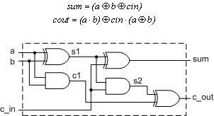
그림 5.6. 1-bit full adder
Ex)
// 1-bit full
adder
module fulladd(sum, c_out, a, b, c_in);
output sum,
c_out; // I/O port declaration
input a, b, c_in;
wire s1, c1, c2;
xor (x1, a,
b);
and (c1, a, b);
xor (sum, s1,
c_in);
and (c2, s1, c_in);
or (c_out, c2, c1);
endmodule
- 4-bit ripple carry full adder 는 4 개의 1-bit full adder로 만들 수 있다.
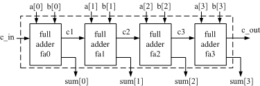
그림 5.7 4-bit full adder
Ex)
// 4-bit full
adder
module fulladd4(sum, c_out, a, b, c_in);
output [3:0]
sum;
output c_out;
input [3:0] a,
b;
input c_in;
wire c1, c2, c3;
fulladd fa0(sum[0],
c1, a[0], b[0], c_in);
fulladd fa1(sum[1], c2, a[1], b[1],
c_1);
fulladd fa2(sum[2], c3, a[2], b[2],
c_2);
fulladd fa3(sum[3], c_out, a[3], b[3],
c_3);
endmodule
Ex)
//
Stimulus for 4-bit full adder
module stimulus;
reg[3:0] A,
B;
reg C_IN;
wire [3:0]
SUM;
wire C_OUT;
fulladd4 FA1_4(SUM, C_OUT, A, B, C_IN);
initial
begin
$monitor($time, "A= %b, B=
%b, C_IN= %b, --- C_OUT= %b, SUM= %b\n", A, B, C_IN, C_out,
SUM);
end
initial
begin
A = 4'd0; B = 4'd0; C_IN =
1'b0;
#5 A = 4'd3; B = 4'd4;
#5 A = 4'd2; B = 4'd5;
#5 A = 4'd9; B = 4'd9;
#5 A = 4'd10; B = 4'd15;
#5 A = 4'd10; B =
4'd5; C_IN = 1'b1;
end
endmodule
- 시뮬레이션 결과
0 A= 0000, B= 0000, C_IN= 0, --- C_OUT= 0, SUM = 0000
5 A= 0011, B= 0100, C_IN= 0, --- C_OUT= 0, SUM = 0111
10 A= 0010, B= 0101, C_IN= 0, --- C_OUT= 0, SUM = 0111
15 A= 1001, B= 1001, C_IN= 0, --- C_OUT= 1, SUM = 0010
20 A= 1010, B= 1111, C_IN= 0, --- C_OUT= 1, SUM = 1001
25 A= 1010, B= 0101, C_IN= 1, --- C_OUT= 1, SUM = 0000
5.2 Gate Delays
- 지금까지 gate의 delay에 대한 고려는 없었지만, 실제 H/W에서는 delay를 고려하여 설계해야 한다.
- primitives들도 delay에 대한 특성을 지정하여 줄 수 있다.
5.2.1 Rise, Fall, Turn-off Delays
- Rise delay : 0, x, z에서 1로 transition되는데 까지 걸리는 시간.
- Fall delay
: 1, x, z에서 0으로 transition되는데 까지 걸리는 시간.
-
Turn-off delay : 0, 1에서
z로 trnasition되는데 까지 걸리는 시간.
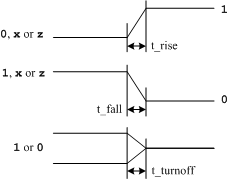
그림 5.8 Delays
- delay를 지정해 주는 방법도 세가지가 있다.
- 1개의 delay : Rise, Fall,
Turn-off모두 동일하게 지정
- 2개의 delay : (rise, fall) 과 같이 앞에 있는 것이 rise, 뒤의 것이
fall이다. 이때 turn-off delay는 둘 중 작은것이 된다.
- 3개의 delay : (rise, fall,
turn-off)로 각각 지정할 수 있다.
- delay를 지정하지 않으면 모든 delay는 0이 된다.
Ex)
//Delay 지정
방법
and #(delay_time) a1(out, i1, i2); //
rise, fall, turn-off = delay_time
and #(rise_val, fall_val) a2(out, i1, i2); // rise = rise_val, fall = fall_val,
// turn-off = min(rise_val, fall_val)
bufif0
#(r_time, f_time, to_time) b1(out, in, ctrl); // 각각
지정(순서유의)
and #(5) a1(out, i1,
i2);
// 모든 delay는 5
and #(4,6) a2(out, i1,
i2); // rise =
4, fall = 6, turn-off = 4
bufif0 #(3,4,5) b1(out, in,
ctrl); // rise=3, fall=4, turn-off=5
5.2.2 Min/Typ/Max Values
- 위에서 언급한 세가지의 delay에 대하여 최소값, 최대값, 보통값을 지정해 놓을 수 있다.
- 시뮬레이션
과정에서 세가지 delay category중 하나를 선택하여 시뮬레이션 해볼 수 있게 된다.
- Verilog-XL 시뮬레이터의
경우 +maxdelays, +typdelays, +mindelays의 옵션으로 delay옵션을 선택할 수 있다.
Ex)
//delay
sets
// rise delay = 3(min) : 4(typ) :
5(max)
// fall delay =
2(min : 3(typ) : 4(max)
// turn-off delay = 4(min) :
5(typ): 6(max)
and #(3:4:5, 2:3:4:,
4:5:6) a1(out, i1, i2);
>verilog test.v +maxdelays -> test.v를 maxdelay값으로 시뮬레이션하라.
(Verilog-XL 시뮬레이터)
5.2.3 Daely Example

그림 5.9 Module D
Ex)
// Module
D
modue D (out, a, b, c);
output out;
input a, b,
c;
wire e;
and #(5) a1(e, a,
b);
or #(4) o1(out, e, c);
endmodule
Ex)
// Stimulus
for module D
module stimulus;
reg A, B,
C;
wire OUT;
D d1(OUT, A, B, C);
initial
begin
A = 1'b0; B = 1'b0; C =
1'b0;
#10 A = 1'b1; B = 1'b1; C = 1'b1;
#10 A = 1'b1; B = 1'b0; C = 1'b0;
#20
$finish;
end
endmodule
- 위의 시뮬레이션을 실행시켜 waveform을 얻으면 다음과 같다
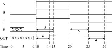
그림 5.10 Waveform of delay simulation