Verilog HDL
2007/06/25 14:24
http://blog.naver.com/PostPrint.nhn?blogId=babojay&logNo=40039111521#
Chapter 6.
Dataflow Modeling
- 작은 회로의 경우는 gate의 수가 제한적이며 하나 하나 gate instantiation을 하고 연결을 할 수 있기 때문에 Gete-level modeling으로도 충분하다. 더구나 기초적인 디지털 회로 지식만 있다면 설계방법이 매우 직관적일 수 있다. 하지만 회로가 복잡해지고 gate수가 늘어나면서 더 효율적인 설계 방법이 필요하였다. Dataflow modeling은 레지스터간 데이터의 이동과 그 데이터의 처리에 관하여 기술하는 설계 방법이다. 요즘엔 Logic synthesizer의 발전으로 Dataflow modeling을 자동으로 Gate-level modeling으로 변환해 주면서 Dataflow Modeling이 더욱 각광을 받고 있다. 설계과정의 유연함을 극대화하기 위하여 Gate-level, Dataflow, Behavioral 설계개념을 아우르는 Verilog Description이 대세이며, Dataflow와 Behavioral의 조합인 RTL(Register Tansfer Level)설계 방법이 일반화되었다.
*Objectives
- assign(continuos
assignment)구문 , assign 구문의 제한, Implicit assignment 구문
- Assignment
delay, Implicit assignment delay, Net declaration delay
- Expressions,
Operators, Operands
- Operator types - 수학, 논리, 관계, 등가, bitwise,
reduction, shift, concatenation,
conditional
6.1 Continuous
Assignments
- Dataflow modeling에서 가장 기본적인
구문이다.
- Continuous란 연속적이다. 끊김이 없다라는 뜻이다. H/W에서는 어떤 의미일까? 시간에 대한 연속일
것이다. 다시 말하면 assigning 중에 저장하는 과정이 없다는 말이다. register나 latch의 기능이 없는 digital
회로 개념에서는 조합회로(combinational)이라고 하면 비슷할 것이다.
Syntax]
<continuous_assign>
::=
assign <drive_strength>?<delay>?
<list_of_assignment>;
- <drive_strength>?,
<delay>? 는
option이다.
- drive_strength는 strength
level로 지정해 줄 수 있으며 기본값은 strong1,
strong0이다.
- delay는 시간단위로 지정해줄 수 있다.
continuous assginment의 특징을 정리하면 다음과 같다.
1. assign의 왼쪽에 올 수 있는 것은 net이다. register는 올 수
없다.
2. delay를 포함하여 오른쪽의 변화가 결정되어짐과 동시에
assign된다.
3. 오른쪽에는 net, register, function call등이 올 수
있다.
4. Delay를 지정해 줄 수 있으며, 이는 gate delay를 정하는 것과 유사하다.
Ex)
// out, i1, i2
는 모두 net
assign out = i1 & i2;
// addr는 16-bit
vectorr net, addr1과 addr2는 16-bit register
assign
addr[15:0] = addr1[15:0] ^ addr2[15:0];
// Concatenation.
c_out과 sum[3:0]이 합쳐져 5-bit net으로 간주된다.
assign {c_out,
sum[3:0]} = a[3:0] + b[3:0] + c_in;
6.1.1 Implicit Continuous Assignment
- 다음의 예처럼 net을 선언하면서 암묵적으로 assign이 이루어지기도 한다.
Ex)
// 보통의
예
wire out;
assign out = in1 &
in2;
// Implicit
Assign
wire out = in1 & in2;
6.2 Delays
6.2.1 Regular Assignment Delay
- assign
키워드 뒤에 time unit으로 명시해준다.
- 오른쪽의 operand의 변화가 생길때 delay만큼의 시간후에 수식을
재계산하여 결과에 반영하게 된다.
Ex)
assign #10
out = in1 & in2;
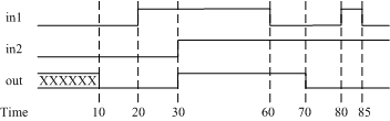
그림 6.1 Delays
- 20 에서 in1과 in2가 'H'로 올라가고 그 결과가 10뒤인 30에
나타난다.
- 마찬가지로 60에 in1이 'L'로 내려오고 그 결과가 70에
나타난다.
- 80에 in1이 'H'로 올라갔으나 delay time 10이
흐른 90에 결과를 재계산하게 돤다. 하지만 delay time이 10이 되기 전에 'L'로
내려갔기 때문에 90에서 재계산 결과는 'L'이 된다.
- 이런 이유로
inertial delay(관성 딜레이)라고도 한다.
6.2.2 Implicit Continuous Assignment Delay
Ex)
// Implicit
delay
wire #10 out = in1 & in2;
6.2.3 Net Declaration Delay
- Net를 선언할 때 그 net에 delay를 지정할 수 있다.
Ex)
// Net
Delay
wire #10 out;
assign out = in1
& in2;
6.3 Expressions, Operators and Operands
6.3.1 Expressions
- 피연산자와 연산자로 이루어져 결과를 갖는 일종의
수식.
Ex)
//
Expressions
a ^ b
addr1[20:17] +
addr2[20:17]
in1 | in2
6.3.2 Operands
- Constant, integer, real number,
net, register, times, bit-select, part-select등 거의 모든 data type과 memory, function
call도 가능하다.
Ex)
//
Operands
integer count, final_count
final_count = count + 1; // count : integer operand, 1 :
constant operand
real a, b,
c;
c = a -
b; // a, b : real
operand
reg [15:0] reg1,
reg2;
reg [3:0] reg_out;
reg_out =
reg1[3:0] ^ reg2[3:0]; // reg1[3:0], reg2[3:0]: part-select operand
reg
ret_value;
ret_value = calculate_parity(A,
B); // function call(calculate_parity) operand
6.4 Operator Types
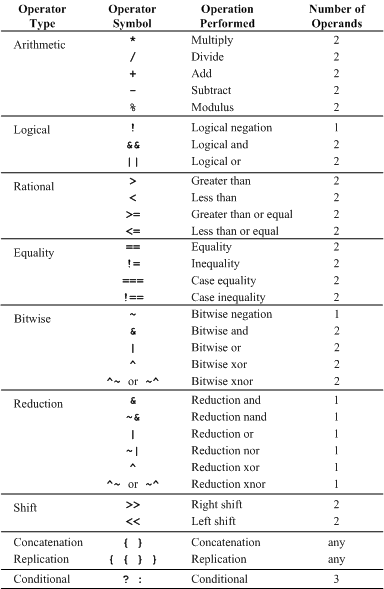
표 6.1 Operator types
6.4.1 Arithmetic Operators
- Binary operator : 2개의
operand를 가지는 operator
Ex)
A * B //
곱하기.
D / E //
나누기
A + B // 더하기
B
- A // 빼기.
D % E //
나머지. (modulus)
in1 = 4'b101x; in2 =
4'b1010;
sum = in1 + in2; // sum :
4'bx
13 % 3 //
modulus operator(나머지) 결과는 1
-7 % 2 //
-1
7 % 2 // 1
- Unary operator : operand앞에 붙는 +, -
Ex)
-4 // negative 4
+5 // positive 5
-10 /
5 // 결과는 -2
-'d10 /
5 // 결과는 정확하지 않으며 예측할 수 없게
된다.
// -'d10 -> 2'comp of 10 -> 2^32 - 10
6.4.2 Logical Operators
- and(&&), or(||), not(!): &&, || 는 binary, ! 는
unary이다.
- 연산의 결과는 항상 1-bit의 true(1),
false(0), x 로
나타난다.
- 연산의 결과가 0 이면 false, 0이
아니면 true가 되지만, operand중 어느하나라도 x나 z를
갖고 있다면 결과는 x가 된다.
Ex)
// Logical
operation
A = 3; B = 0;
A &&
B // (true AND false)의 관계이므로 결과는
false(0)이다.
A || B // (true OR
false)의 관계이므로 결과는 true(1)이다.
!A // NOT(true)이므로 결과는
false(0)이다.
!B
// NOT(false)이므로 결과는 true(1)이다.
A = 2'b0x; B =
2"b10;
A && B
// (x AND true)이므로 결과는 x
(a == 2) && (b == 3) // a=2, b=3인 경우에만 true(1), 그 이외는 false(0)
6.4.3 Relation operator
- 크고( >) 작고(<) 크거나 같고(>=) 작거나 같고(<=)의 관계를 구한다.
Operand중에 x나z가 존재하면 그
수식의 결과는 x가 된다.
Ex)
// A = 4, B =
3
// S = 4'b1010, T = 4'b1101, U = 4'b1xxx
A <=
B // 결과는 0
A >
B // 결과는 1
T
>= S // 결과는 1
T <
U // 결과는 x
6.4.4 Equality Operator
- Logical equality(==, !=)와 case equality(===, !==)의 두가지가
존재한다.
- Logical equality는 논리 연산의 결과를 따진다. 즉, operand에 x,
z가 존재하면 결과는 x가 된다.
- Case equality는 논리 연산과는
무관하게 operand가 무슨 값이든 일대일로 동일한지의 여부만 따진다.
Ex)
// A = 4, B =
3
// J = 4'b1010, K = 4'b1101
// S =
4'b1xxz, T = 4'b1xxz, U = 4'b1xxx
A ==
B // false
J !=
K // true
J ==
S // x(unknown)
S ===
T // true
T !== U //
true
6.4.5 Bitwise Operators
- bit단위의 논리
연산이다.
- operand의 bit수가 다른 경우 작은 bit수의 MSB쪽으로 0이 채워 큰 쪽과 같게 만든다.
- 연산의 결과는 bit에만 한정되며 다른 bit에
영향을 주지 않는다.
Ex)
// A =
4'b1010, B = 4'b1101, C = 4'b10x1
~A //
4'b0101
A & B //
4'b1000
A | B //
4'b1111
A ^ B //
4'b0111
A ^~ B //
4'b1000
A & C //
4'b10x0
6.4.6 Reduction Operators
- 하나의 operand내의 bit들과의 논리연산으로 결과는 1-bit이다.
- &, ~&, |,
~|, ^, ~^(^~) 등binary operator이지만 사용법은 unary
operator이다.
Ex)
// A =
4'b1010
&A // 1 & 0 & 1 & 0 ->
1'b0
|A // 1 | 0 | 1 | 0
-> 1'b1
^A // 1 ^ 0 ^ 1 ^
0 -> 1'b0
6.4.7 Shift Operators
- 오른쪽이나 왼쪽으로 명시한 만큼 bit를 옮기는 연산자
- 옮기면서 생기는 빈 자리는 0으로
채워진다.
Ex)
// A =
4'b1100
Y = A >>
1; // 4'b0110
Y = A <<
1; // 4'b1000
Y = A <<
2; // 4'b0000
6.4.8 Concatenation Operator
- size가 명시된 operand만
사용 가능하다.
- net, reg, vector, bit-select, part-select, sized constant등을
하나로 연결하는 연산자 ( {, }
)
Ex)
// A = 1'b1, B
= 2'b00, C = 2'b10, D = 3'b110
Y = {B,
C};
// Y = 4'b0010
Y = {A, B, C, D,
3'b001}; // Y = 11'b1_00_10_110_001
Y =
{A, B[0], C[1]}; //
Y = 3'b101
6.4.9 Replication Operator
- Concatenation의
operand를 몇 번 반복해서 넣을 것인가 지정하는 연산자
Ex)
reg
A;
reg [1:0] B, C;
reg [2:0]
D;
A = 1'b1; B = 2'b00: C = 2'b10; D = 3'b110;
Y = { 4{A}
};
// Y = 4'b1111
Y = { 4{A}, 2{B}
}; // Y =
8'b11110000
Y = { 4{A}, 2{B}, C }; // Y
= 11'b11110000110
6.4.10 Conditional Operator
- Condition_expr ? true_expr :
false_expr;
- Condition_expr를 면저
계산하고 그 결과가 true이면 true_expr가 실행되고, false이면 false_expr가 실행된다.
- Condition_expr가 x일 경우, true_expr, false_expr모두 계산하여
결과를 bit단위로 비교한다. 같으면 그 값으로, 다르면 x로 결정된다.
-
true_expr, false_expr는
각각 conditional operation이 들어갈 수 있다. 즉 nesting이 허용된다.
Ex)
// modeling
tristate buffer
assign addr_bus = drive_enable ? addr_out
: 36'bz;
// modeling 2-to-1
mux
assign out = control ? in1 : in0;
//
nesting
assign out = (A == 3) ? (control ? x : y) :
(control ? m : n);
6.4.11 Operator Precedence
- 각 연산자들의 우선순위는 다음과 같다.
- 코드를 읽기 쉽게 하기 위해 괄호를 적절히 사용하여 주는 것이
좋다.
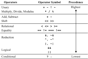
표 6.2 Operator Precedence
6.4 Examples
- 전에 다루었던 4-to-1 multiplexer와 4-bit full adder를 dataflow를 이용하여 modeling하여 본다.
6.5.1 4-to-1 Multiplexer
- Method 1: Logic Equation
Ex)
// 4-to-1
Multiplexer with Dataflow, Logic Equation
module mux4_to_1
(out, i0, i1, i2, i3, s1, s0);
output
out;
input i0, i1, i2, i3;
input s1,
s0;
// Logic equation for
out
assign out = (~s1 & ~s0 & i0)
|
(~s1 & s0 & i1)
|
(s1 & ~s0 & i2)
|
(s1 & s0 & i3);
endmodule
- Method 2: Conditional Operator
Ex)
// 4-to-1
Multiplexer with Dataflow, Conditional Operator
module
mux4to1( out, i0, i1, i2, i3, s1, s0);
output
out;
input i0, i1, i2, i3;
input s1,
s0;
// Nested conditional
operator
assign out = s1 ? (s0 ? i3 : i2) : (s0 ? i1 :
i0);
endmodule
- 참고로 Chapter 5에서 gate-level로 modeling 했던 예제를 비교해본다.
Ex)
// 4-to-1 MUX
in Gate-level description
module mux4_to_1(out, i0, i1,
i2, i3, s1, s0);
output
out;
// Port declaration
input i0, i1, i2,
i3;
input s1, s0;
wire s1n,
s0n;
// Internal wire
wire y0, y1, y2, y3;
not (s1n,
s1);
// create s1n, s0n
not (s0n, s0);
and (y0, i0, s1n,
s0n); // 3-input and gate
and (y1,
i1, s1n, s0);
and (y2, i2, s1, s0n);
and (y3, i3, s1, s0);
or (out, y0, y1, y2, y3); // 4-input or gate
endmodule
6.5.2 4-bit Full Adder
- Method 1: Dataflow Operator
Ex)
// 4-bit Full
Adder with dataflow statement
module fulladd4 (sum, c_out,
a, b, c_in);
output [3:0]
sum;
output c_out;
input [3:0] a,
b;
input c_in;
assign {c_out, sum} = a + b + c_in;
endmodule
- Method 2: full addder with carry lookahead
Ex)
module
fulladd4 (sum, c_out, a, b, c_in);
output [3:0]
sum;
output c_out;
input [3:0] a,
b;
input c_in;
wire p0, g0, p1, g1,
p2, g2, p3, g3;
wire c4, c3, c2, c1;
assign p0 = a[0] ^
b[0],
p1 = a[1] ^
b[1],
p2 = a[2] ^
b[2],
p3 = a[3] ^ b[3];
assign g0 = a[0]
&
b[0],
g1 = a[1] &
b[1],
g2 = a[2] &
b[2],
g3 = a[3] & b[3];
assign c1 = g0 | (p0
&
c_in),
c2 = g1 | (p1 & g0) | (p1 & p0 &
c_in),
c3 = g2 | (p2 & g1) | (p2 & p1 & g0) | (p2 & p1 & p2 &
c_in),
c4 = g3 | (p3 & g2) | (P2 & p2 & g1) | (p3 & p2 & p1 &
g0) |
(p3 & p2 & p1 & p0 & c_in);
assign sum[0] = p0 ^
c_in,
sum[1] = p1 ^
c1,
sum[2] = p2 ^
c2,
sum[3] = p3 ^ c3;
assign c_out = c4;
endmodule
* 4 단계의 gate를 거치면서 propagation delay가 일정하게 된다.
**
logic 은 복잡해지지만 bit수가 늘어나더라도 propagation delay는 늘어나지 않는다.
6.5.3 Ripple Counter
- 전에 다루었던 4-bit ripple counter를 dataflow의 구문으로 modeling 해본다.
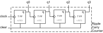
그림 6.2 4-bit Ripple Carry Counter
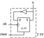
그림 6.3 T-flipflop
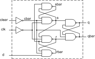
그림 6.4 Negative Edge Triggered D-F/F
Ex)
// 4-bit
Ripple Counter
module counter (Q, clock,
clear);
output [3:0]
q;
input clock, clear;
T_FF tff0 (q[0],
clock, clear);
T_FF tff1 (q[1], q[0],
clear);
T_FF tff2 (q[2], q[1],
clear);
T_FF tff3 (q[3], q[2], clear);
endmodule
// Edge-triggered
T-F/F
module T_FF (q, clk, clear);
output
q;
input clk, clear;
edge_dff ff1(q, , ~q,
clk, clear); // instantiation of
edge_dff
// complement of q is fed back to
d
// qbar is not connected
endmodule
// Edge-triggered
D-F/F
module edge_dff (q, qbar, d, clk, clear);
output q,
qbar;
input d, clk, clear;
wire s, sbar, r, rbar, cbar;
assign cbar =
~clear;
assign sbar = ~(rbar &
s),
s = ~(sbar & cbar &
~clk),
r = ~(rbar & ~clk,
s),
rbar = ~(r & cbar & d);
assign q = ~(s &
qbar),
qbar = ~(q & r & cbar);
endmodule
- Stimulus block
Ex)
// Top level
stimulus module
module stimulus;
reg CLOCK,
CLEAR;
wire [3:0] Q;
initial
$monitor($time, " Count Q
= %b, Clear = %b", Q[3:0], CLEAR);
counter c1(Q, CLOCK, CLEAR);
initial
begin
CLEAR =
1'b1;
#34 CLEAR =
1b0;
#200 CLEAR =
1'b1;
#50 CLEAR =
1'b0;
end
initial
begin
CLOCK =
1'b0;
forever #10 CLOCK =
~CLOCK;
end
initial
begin
#400
$finish;
end
endmodule
- 시뮬레이션 결과
0
Count Q = 0000, Clear = 1
34 Count Q = 0000, Clear = 0
40 Count Q = 0001, Clear =
0
60 Count Q = 0010, Clear
= 0
80 Count Q = 0011,
Clear = 0
100 Count Q = 0100,
Clear = 0
120 Count Q = 0101,
Clear = 0
140 Count Q = 0110,
Clear = 0
160 Count Q = 0111,
Clear = 0
180 Count Q = 1000,
Clear = 0
200 Count Q = 1001,
Clear = 0
220 Count Q = 1010,
Clear = 0
234 Count Q = 0000,
Clear = 1
284 Count Q = 0000,
Clear = 0
300 Count Q = 0001,
Clear = 0
320 Count Q = 0010,
Clear = 0
340 Count Q = 0011,
Clear = 0
360 Count Q = 0100,
Clear = 0
380 Count Q = 0101,
Clear = 0