Record #2586
Product Family: Software
Product Line: Timing
Problem Title:
VIRTEX CLKDLL TIMING for 1.5i
Problem Description:
Keywords: Timing, CLKDLL, CLKDLLHF, Constraints Editor
Urgency: Standard
General Description: What are the issues associated with constraining
the paths of the
various taps of the DLLs? In addition, how do TRCE and Timing Analyzer
handle constraints
and the various taps of the DLL?
CLKDLL Documentation:
For more information about the CLKDLL implementation, refer to the following
documents.
XAPP132: Using the Virtex Delay-Locked Loop http://www.xilinx.com/apps/virtexapp.htm
Libraries Guide: http://toolbox.xilinx.com/docsan/data/alliance/lib/lib4_22.htm
Timing Constraints:
The CLKDLL provides many powerful features that aid in the design of high-speed
digital circuits. Associated
with these features is the ability of the Xilinx tool set to perform
timing based place and route. PERIOD, OFFSET,
and FROM TO constraints will be illustrated in detail. Figure 1 contains
one implementation of the CLKDLL.
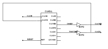
Figure 1. CLKDLL Implementation.
PERIOD
A PERIOD constraint can be applied to the DLL in figure 1 in the following
ways.
Using the pad net name method:
NET "PADCLKIN" PERIOD = 30 ns;
Using the DLL output net name method:
NET "ZERO" PERIOD = 30 ns;
Or
NET "ZERO" TNM_NET = "ZERO";
TIMESPEC TS_ZERO = PERIOD "ZERO" 30 ns;
Note: TNM_NET does not propagate through the CLKDLL.
Both methods will constrain the net ZERO the same way. However the way
that TRCE/TA reports the two
constraints is different. An example of timing report for each method
will be included below.
Using the pad net name method:
=======================================================================
Timing constraint: NET "PADCLKIN"
PERIOD = 30 nS HIGH 50.000 % ;
0 items analyzed, 0 timing errors
detected.
-----------------------------------------------------------
The original PERIOD constraint reports 0 items analyzed. However, TRCE/TA
creates another PERIOD
constraint for each DLL output based upon the original PERIOD. Each
of the new PERIOD constraints is
adjusted depending on the output. For example a 30ns PERIOD on the
input is changed to a 15ns PERIOD
on the 2X output.
=======================================================================
Timing constraint: PERIOD *
2 analysis for net "TWOTIME" derived from
NET "PADCLKIN" PERIOD = 30 ns
HIGH 50.000 % ;
144 items analyzed, 0 timing
errors detected.
Minimum period is 9.015ns.
-----------------------------------------------------------------------
Slack: 5.985ns path PADCE to
&__A__80 relative to
15.000ns delay constraint
Using the DLL output net name method:
=======================================================================
Timing constraint: TS_TWOTIME
= PERIOD TIMEGRP "TWOTIME" 30 ns HIGH 50.0%;
348 items analyzed, 141 timing
errors detected.
Minimum period is 14.690ns.
-----------------------------------------------------------------------
Slack: -7.112ns path &__A__70
to U3/BU3 relative to
10.131ns skew between &__A__70
and U3/BU3
Note: If the CLKDV output is used with a division factor (CLKDV_DIVIDE)
of 1.5 or 2.5, then a
PERIOD based upon the CLKDV output net must be used. Timing Engine
does not properly propagate
PERIOD constraints in this situation.
The CLKDLL provides duty cycle correction on all 1x clock outputs such
that all 1x outputs by default
have a 50/50 duty cycle. The DUTY_CYCLE_CORRECTION property (TRUE by
default), controls
this feature. This should be kept in mind when creating period constraints
based upon the DLL outputs.
For example:
Original Constraint: NET "ZERO" PERIOD = 30 ns HIGH 7 ns;
Modified Constraint: NET "ZERO" PERIOD = 30 ns HIGH 15 ns;
The modified constraint accounts for the duty cycle correction. Duty cycle
correction also occurs on the 2x and
DV outputs. This correction can not be controlled by the property.
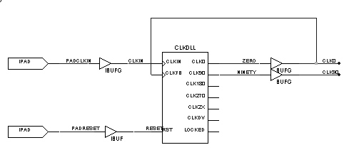
Figure 2.CLKDLL Implementation
PAD to SETUP (OFFSET IN BEFORE):
When creating pad-to-setup requirements, care should be taken to incorporate
any phase or PERIOD adjustment
factor into the value specified for an OFFSET IN constraint.
Figure 3. Schematic Layout
For example: If your register is clocked by the net from the CLK90 pin
of the DLL which has a PERIOD of 20ns,
then the OFFSET value should be adjusted by an additional 5 ns.
Original Constraint: NET "PAD_IN" OFFSET = IN 10 BEFORE "PADCLKIN";
Modified Constraint: NET "PAD_IN" OFFSET = IN 15 BEFORE "PADCLKIN";
NOTE: The clock net name required for OFFSET constraints is the clock net
name attached to the IPAD. In this
case it is PADCLKIN not CLK90, refer to fig 2 for the clk network.
CLOCK to PAD (OFFSET OUT AFTER):
When creating clock-to-pad requirements, care should be taken to incorporate
any phase or PERIOD adjustment
factor into the value specified for an OFFSET OUT constraint. For example:
If your register is clocked by the net
from the CLK90 pin of the DLL which has a PERIOD of 20ns, then the
OFFSET value should be adjusted by 5 ns
less than the original constraint.
Original Constraint: NET "PAD_OUT" OFFSET = OUT 15 AFTER "PADCLKIN";
Modified Constraint: NET "PAD_OUT" OFFSET = OUT 10 AFTER "PADCLKIN";
FROM TO In Multiple Clock Domains:
 Figure 4. FROM TO Schematic.
When using PERIOD constraints, the user must properly constrain the paths
between multiple clock domains. Refer
Figure 4. FROM TO Schematic.
When using PERIOD constraints, the user must properly constrain the paths
between multiple clock domains. Refer
to figure 4. If a PERIOD constraint is applied to the CLK90 and CLK0
output pins of the DLL, the CLK0 PERIOD
constraint will constrain the paths between flip-flop A and B. This
type of constraining can lead to setup violations.
Consider the waveforms in figure 5. Because of the phase shift between
CLK90 and CLK0, the path from A to B
has 25% less time than the PERIOD constraint allows. To properly constrain
these paths use a FROM TO constraint.
For Example:
NET "CLK90" TNM_NET = "CLK90";
NET "CLK0" TNM_NET = "CLK0";
TIMESPEC "TS_CLK90_2_CLK0" = FROM "CLK90" TO "CLK0" 15ns;
The TIMESPEC is set at 15ns because the PERIOD on CLK0 is 20ns.
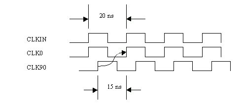
Figure 5. Waveform illustration of CLKIN, CLK0, and CLK90.
This type of correction is required for all clock domain interactions.
The following table contains the some
of the possible configurations and the associated corrections.
|
CLKDLL
|
Required Correction
|
|
CLK0 to CLK90
|
Subtract 75%
|
|
CLK0 to CLK180
|
Subtract 50%
|
|
CLK0 to CLK270
|
Subtract 25%
|
|
CLK270 to CLK0
|
Subtract 75%
|
|
CLK270 to CLK90
|
Subtract 50%
|
|
CLK270 to CLK180
|
Subtract 25%
|
Constraints Editor:
The Constraints Editor handles constraints specific to the CLKDLL
in the following way.
PERIOD:
The Constraint Editor creates PERIOD constraints based upon the DLL
output name method.
Care still needs to be taken with respect to duty cycle correction,
multiplication, and division.
PAD to SETUP and CLOCK to PAD:
When creating pad or register specific OFFSET constraints in the Constraints
Editor the user must
specify the clock pad net name for flip-flops driven by the CLKDLL.
In figure 1, PADCLKIN is
the pad net name used in OFFSET constraints.
FROM:TO:
Groups can be created based upon the DLL outputs and used to create
timespecs to control multiple
clock domain paths.