Answers Database
COREGEN: How to do an impulse response simulation of a SINGLE cascade mode SDA FIR filter

Record #4675
Product Family: Software
Product Line: LogiCore
Product Part: Coregen IP Modules
Problem Title:
COREGEN: How to do an impulse response simulation of a SINGLE cascade mode SDA FIR filter
Problem Description:
Urgency: standard
General Description:
Simulating a single cascade mode SDA FIR filter.
When a single FIR filter is generated in cascade
mode, data is fed into the SINF (serial input forward) port
instead of the parallel DATA input.
Solution 1:
Main Sequence:
- Initialize SINF and ND to 0.
- Assert GSR for one or two clock cycles,
- release for one cycle
- assert ND high on falling edge of clock for one cycle and release;
- assert SINF high on falling edge of clock at the same
time ND is deasserted. Assert for one cycle and release.
Repeating subsequence:
One cycle after RFD goes high, repeat:
- assert ND high on falling edge of clock for one cycle and release.
- assert SINF high on falling edge of clock at the same
time ND is deasserted. Assert for one cycle and release.
Repeat the "subsequence" of steps (each time RFD goes high)
for as many cycles as needed and observe the output at the
RSLT port. The RSLT output is valid when RDY is high, for
the full duration of its assertion.
Note that for a *single* casdade mode filter, there is
a one-clock cycle delay between the assertion of ND and
SINF to compensate for the absence of a parallel-to-serial
converter at the front of the filter when cascade mode is
selected. The timing diagram (Figure 3 ) in the SDA FIR data
sheet does not apply in this situation.
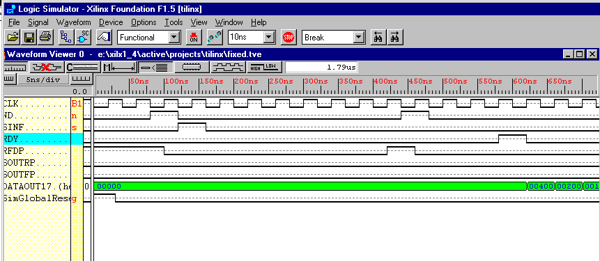
Figure 1 below shows a sample simulation session using the
Foundation gate level simulator.

Figure 1- Simulation of Single Cascade Mode SDA FIR Filter
End of Record #4675 - Last Modified: 09/23/98 19:34 |


