The pre-installed libraries are the ones that are included in the PSpice for TI installation.
Capture identifies the use of parts that contain imported models (which are not in the pre-installed libraries). When such parts are used in the schematic design, the Online DRC window displays a warning.
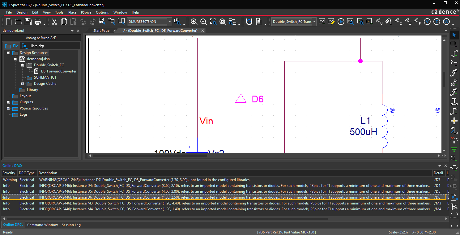
When you run PSpice simulation on such a design (that contains imported models), you will able to place a maximum of three markers for data collection. The marker placed after the third marker is not considered for data collection. It appears without the 's' symbol and in grey after simulation.
The following cases are possible:
Case 1
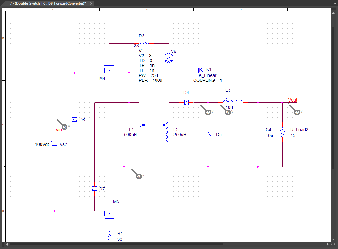
Schematic contains all parts from pre-installed libraries. The simulation starts.
Case 2
Schematic has parts that contain imported models and there is no marker is placed on the design. The simulation does not start and the error message indicates that at least one marker needs to be placed.
Case 3
Schematic has parts that contain imported models and has up to three markers for data collection. The simulation starts.
Case 4
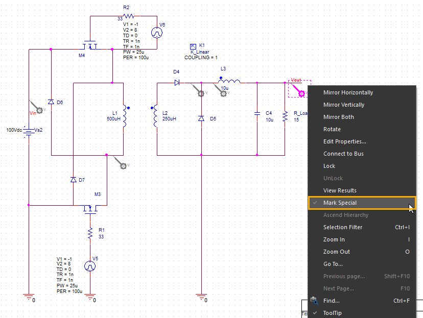
Schematic has parts that contain imported models and has more than three markers for data collection.
Do one of the following for Case 4:
- Select PSpice – Markers – List. From the Markers dialog box, select up to three markers to be used for data collection. Next, click the Run PSpice icon (
 ) to start simulation.
 - Select the marker that is not to be plotted. Right-click this marker and remove selection from Mark Special in the pop-up menu. Next, click the Run PSpice icon () to start simulation.
However, if you do not follow any of the above-listed options (1 or 2), and run simulation with more than three markers for data collection, simulation does not start. You are prompted to select the required three markers to be plotted from the Markers dialog box. This is explained in the following procedure:
- Open the schematic design that has parts, which contain imported models, and more than three markers.
- Click the Run PSpice icon () to simulate the design.
Error message appears indicating that you cannot place more than three markers for data collection.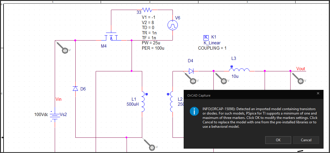
- Click OK.
The Markers dialog box appears.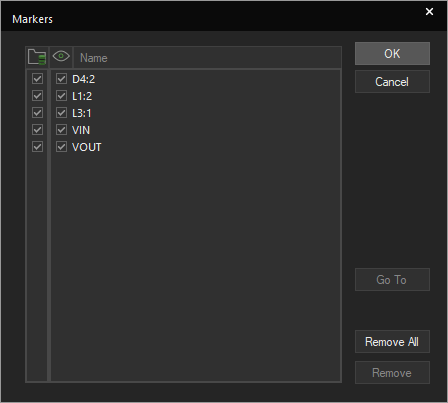
- Select the required markers that need to be saved from the Data Collection column as shown in the following screen shot.
- Click OK.
Simulation starts and you can see the waveform in PSpice.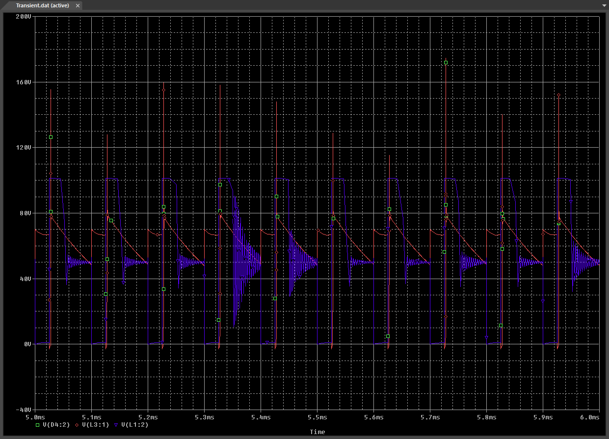
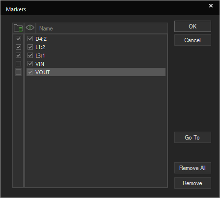
The markers that are not selected in the Markers dialog box appear in grey as shown in the following figure.
The unused markers can also be selected for data collection. To do so:
- Right-click any marker that were used, and disable Mark Special in the pop-up menu.
- Enable Mark Special for any of the unused markers
- Ensure that the number of markers for data collection is three and then run simulation.
Editing and Using Specific Devices
You can edit model parameters for following devices and plot all waveforms for your simulation circuit.
- Passives: R, L, C, K
- Switches: S, W
- Transmission line: T
- Digital stimulus: U - STIM
- Independent sources: V, I
- Controlled sources: E, F, G, H
- Subcircuit: X
For other device types, after editing the models you can plot three markers.