


"DC" stands for Direct Current, which can refer to either voltage or current in a constant polarity or direction, respectively. These experiments are designed to introduce you to several important concepts of electricity related to DC circuits.
PARTS AND MATERIALS
Actually, any size batteries will suffice for this experiment, but it is recommended to have at least two different voltages available to make it more interesting.
CROSS-REFERENCES
Lessons In Electric Circuits, Volume 1, chapter 5: "Series and Parallel Circuits"
Lessons In Electric Circuits, Volume 1, chapter 11: "Batteries and Power Systems"
LEARNING OBJECTIVES
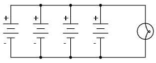
SCHEMATIC DIAGRAM
ILLUSTRATION
INSTRUCTIONS
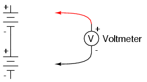
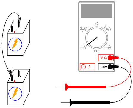
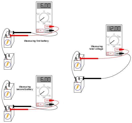
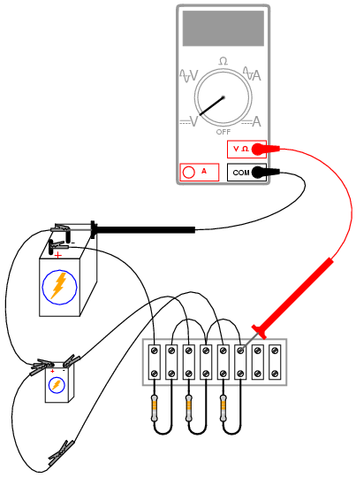
Connecting components in series means to connect them in-line with each other, so that there is but a single path for electrons to flow through them all. If you connect batteries so that the positive of one connects to the negative of the other, you will find that their respective voltages add. Measure the voltage across each battery individually as they are connected, then measure the total voltage across them both, like this:
Try connecting batteries of different sizes in series with each other, for instance a 6-volt battery with a 9-volt battery. What is the total voltage in this case? Try reversing the terminal connections of just one of these batteries, so that they are opposing each other like this:
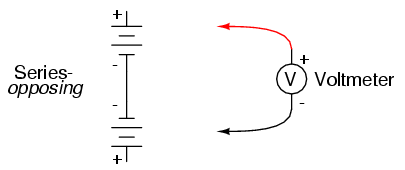
How does the total voltage compare in this situation to the previous one with both batteries "aiding?" Note the polarity of the total voltage as indicated by the voltmeter indication and test probe orientation. Remember, if the meter's digital indication is a positive number, the red probe is positive (+) and the black probe negative (-); if the indication is a negative number, the polarity is "backward" (red=negative, black=positive). Analog meters simply will not read properly if reverse-connected, because the needle tries to move the wrong direction (left instead of right). Can you predict what the overall voltage polarity will be, knowing the polarities of the individual batteries and their respective strengths?
PARTS AND MATERIALS
High-wattage 12-volt lamps may be purchased from recreational vehicle (RV) and boating supply stores. Common sizes are 25 watt and 50 watt. This lamp will be used as a "heavy" load for your batteries (heavy load = one that draws substantial current).
A regular household (120 volt) lamp socket will work just fine for these low-voltage "RV" lamps.
CROSS-REFERENCES
Lessons In Electric Circuits, Volume 1, chapter 5: "Series and Parallel Circuits"
Lessons In Electric Circuits, Volume 1, chapter 11: "Batteries and Power Systems"
LEARNING OBJECTIVES
SCHEMATIC DIAGRAM
ILLUSTRATION
INSTRUCTIONS
Begin this experiment by connecting one 6-volt battery to the lamp. The lamp, designed to operate on 12 volts, should glow dimly when powered by the 6-volt battery. Use your voltmeter to read voltage across the lamp like this:
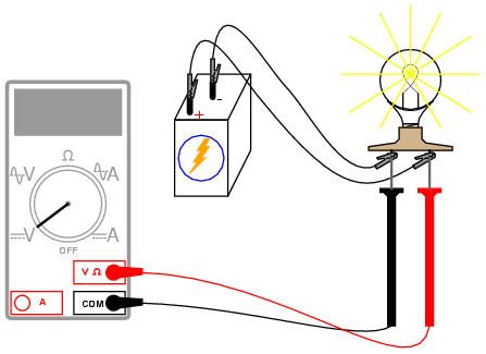
The voltmeter should register a voltage lower than the usual voltage of the battery. If you use your voltmeter to read the voltage directly at the battery terminals, you will measure a low voltage there as well. Why is this? The large current drawn by the high-power lamp causes the voltage at the battery terminals to "sag" or "droop," due to voltage dropped across resistance internal to the battery.
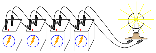
We may overcome this problem by connecting batteries in parallel with each other, so that each battery only has to supply a fraction of the total current demanded by the lamp. Parallel connections involve making all the positive (+) battery terminals electrically common to each other by connection through jumper wires, and all negative (-) terminals common to each other as well. Add one battery at a time in parallel, noting the lamp voltage with the addition of each new, parallel-connected battery:
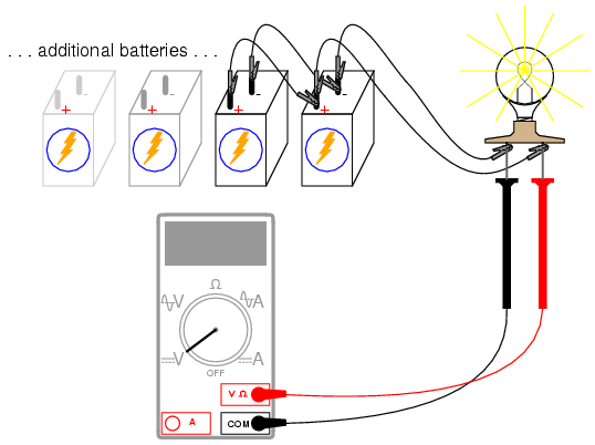
There should also be a noticeable difference in light intensity as the voltage "sag" is improved.
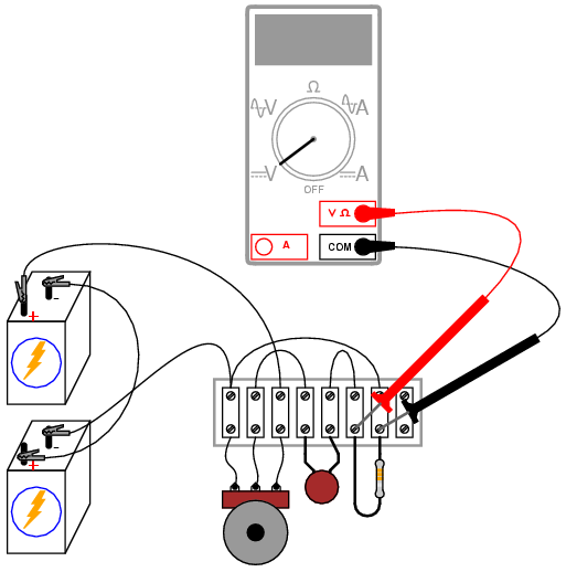
Try measuring the current of one battery and comparing it to the total current (light bulb current). Shown here is the easiest way to measure single-battery current:
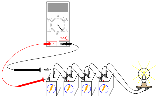
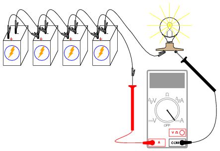
By breaking the circuit for just one battery, and inserting our ammeter within that break, we intercept the current of that one battery and are therefore able to measure it. Measuring total current involves a similar procedure: make a break somewhere in the path that total current must take, then insert the ammeter within than break:
Note the difference in current between the single-battery and total measurements.
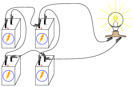
To obtain maximum brightness from the light bulb, a series-parallel connection is required. Two 6-volt batteries connected series-aiding will provide 12 volts. Connecting two of these series-connected battery pairs in parallel improves their current-sourcing ability for minimum voltage sag:
PARTS AND MATERIALS
I'm purposely restricting the resistance values between 1 kΩ and 100 kΩ for the sake of obtaining accurate voltage and current readings with your meter. With very low resistance values, the internal resistance of the ammeter has a significant impact on measurement accuracy. Very high resistance values may cause problems for voltage measurement, the internal resistance of the voltmeter substantially changing circuit resistance when it is connected in parallel with a high-value resistor.
CROSS-REFERENCES
Lessons In Electric Circuits, Volume 1, chapter 6: "Divider Circuits and Kirchhoff's Laws"
LEARNING OBJECTIVES
SCHEMATIC DIAGRAM
ILLUSTRATION
INSTRUCTIONS
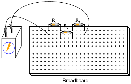
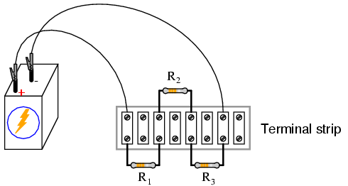
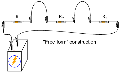
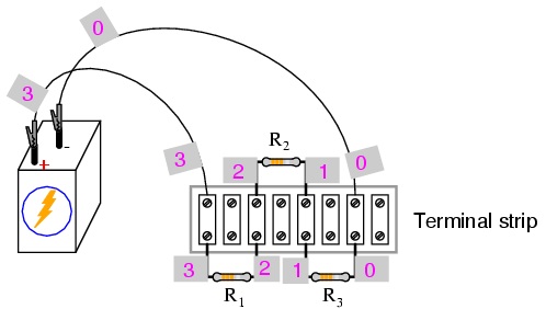
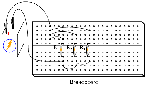
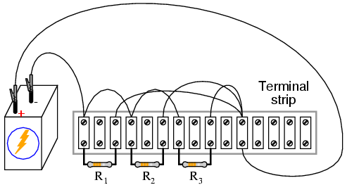
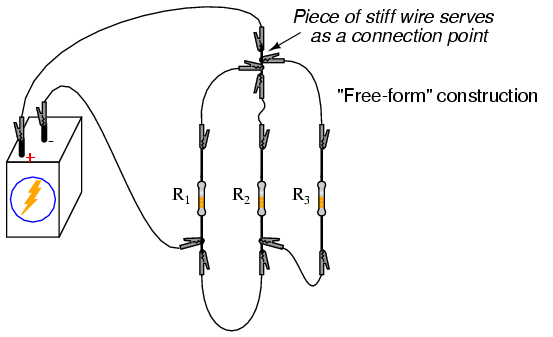
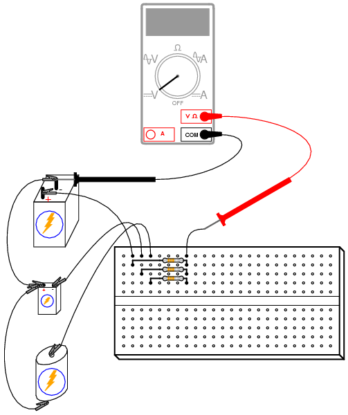
Shown here are three different methods of circuit construction: on a breadboard, on a terminal strip, and "free-form." Try building the same circuit each way to familiarize yourself with the different construction techniques and their respective merits. The "free-form" method -- where all components are connected together with "alligator-" style jumper wires -- is the least professional, but appropriate for a simple experiment such as this. Breadboard construction is versatile and allows for high component density (many parts in a small space), but is quite temporary. Terminal strips offer a much more permanent form of construction at the cost of low component density.
Select three resistors from your resistor assortment and measure the resistance of each one with an ohmmeter. Note these resistance values with pen and paper, for reference in your circuit calculations.
Connect the three resistors in series, and to the 6-volt battery, as shown in the illustrations. Measure battery voltage with a voltmeter after the resistors have been connected to it, noting this voltage figure on paper as well. It is advisable to measure battery voltage while it's powering the resistor circuit because this voltage may differ slightly from a no-load condition. We saw this effect exaggerated in the "parallel battery" experiment while powering a high-wattage lamp: battery voltage tends to "sag" or "droop" under load. Although this three-resistor circuit should not present a heavy enough load (not enough current drawn) to cause significant voltage "sag," measuring battery voltage under load is a good scientific practice because it provides more realistic data.
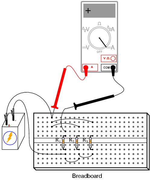
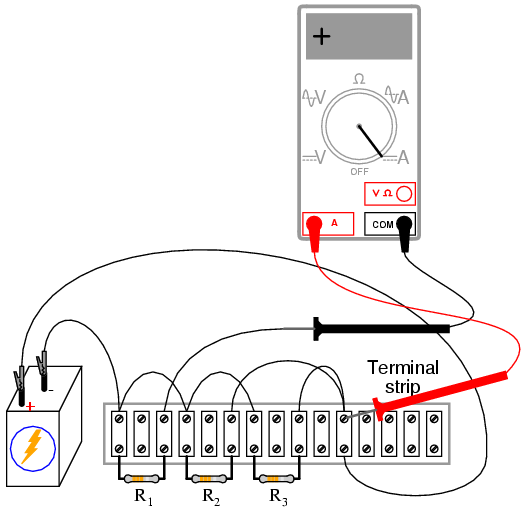
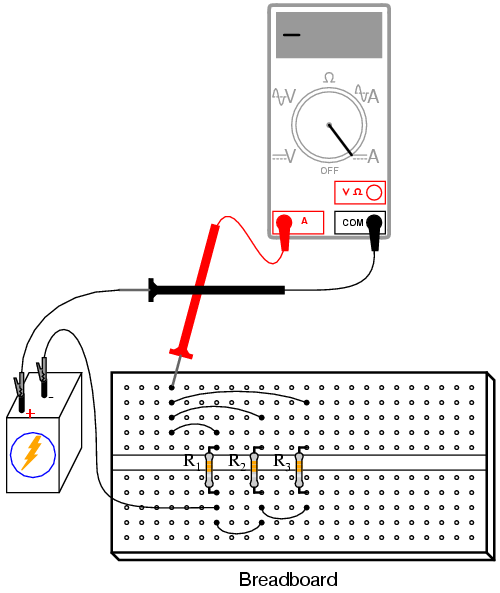
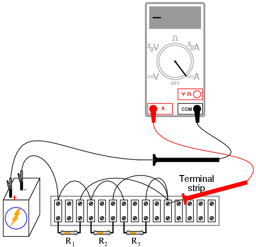
Use Ohm's Law (I=E/R) to calculate circuit current, then verify this calculated value by measuring current with an ammeter like this ("terminal strip" version of the circuit shown as an arbitrary choice in construction method):
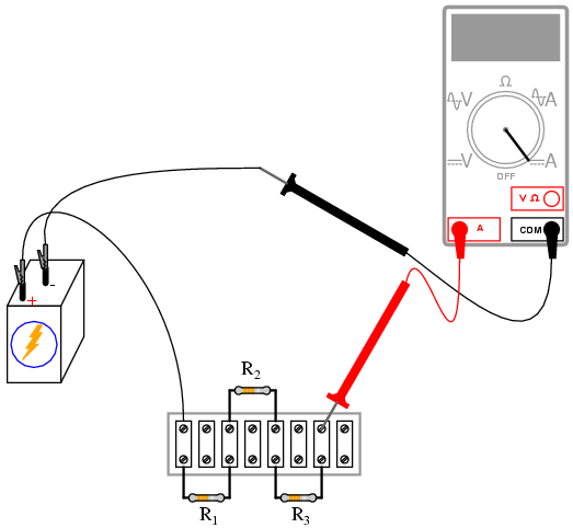
If your resistor values are indeed between 1 kΩ and 100 kΩ, and the battery voltage approximately 6 volts, the current should be a very small value, in the milliamp (mA) or microamp (µA) range. When you measure current with a digital meter, the meter may show the appropriate metric prefix symbol (m or µ) in some corner of the display. These metric prefix telltales are easy to overlook when reading the display of a digital meter, so pay close attention!
The measured value of current should agree closely with your Ohm's Law calculation. Now, take that calculated value for current and multiply it by the respective resistances of each resistor to predict their voltage drops (E=IR). Switch you multimeter to the "voltage" mode and measure the voltage dropped across each resistor, verifying the accuracy of your predictions. Again, there should be close agreement between the calculated and measured voltage figures.
Each resistor voltage drop will be some fraction or percentage of the total voltage, hence the name voltage divider given to this circuit. This fractional value is determined by the resistance of the particular resistor and the total resistance. If a resistor drops 50% of the total battery voltage in a voltage divider circuit, that proportion of 50% will remain the same as long as the resistor values are not altered. So, if the total voltage is 6 volts, the voltage across that resistor will be 50% of 6, or 3 volts. If the total voltage is 20 volts, that resistor will drop 10 volts, or 50% of 20 volts.
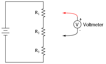
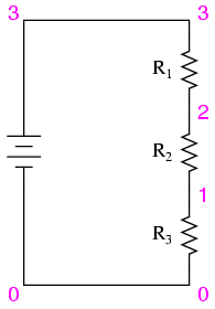
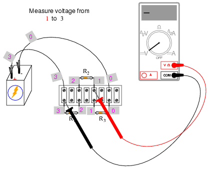
The next part of this experiment is a validation of Kirchhoff's Voltage Law. For this, you need to identify each unique point in the circuit with a number. Points that are electrically common (directly connected to each other with insignificant resistance between) must bear the same number. An example using the numbers 0 through 3 is shown here in both illustrative and schematic form. In the illustration, I show how points in the circuit may be labeled with small pieces of tape, numbers written on the tape:
Using a digital voltmeter (this is important!), measure voltage drops around the loop formed by the points 0-1-2-3-0. Write on paper each of these voltages, along with its respective sign as indicated by the meter. In other words, if the voltmeter registers a negative voltage such as -1.325 volts, you should write that figure as a negative number. Do not reverse the meter probe connections with the circuit to make the number read "correctly." Mathematical sign is very significant in this phase of the experiment! Here is a sequence of illustrations showing how to "step around" the circuit loop, starting and ending at point 0:
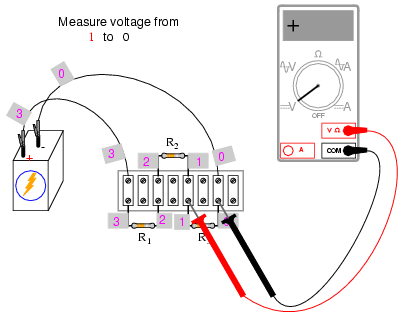
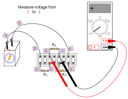
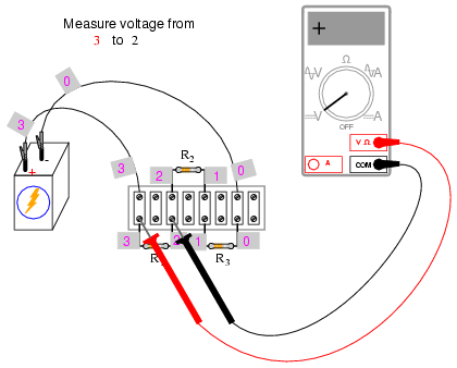
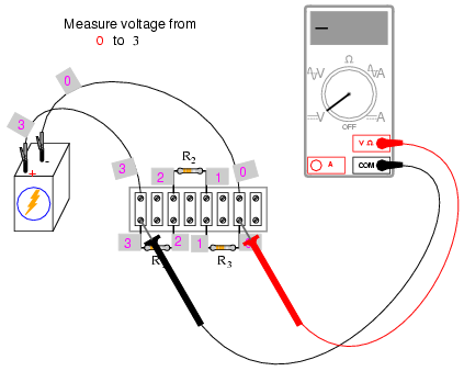
Using the voltmeter to "step" around the circuit in this manner yields three positive voltage figures and one negative:
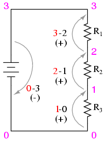
These figures, algebraically added ("algebraically" = respecting the signs of the numbers), should equal zero. This is the fundamental principle of Kirchhoff's Voltage Law: that the algebraic sum of all voltage drops in a "loop" add to zero.
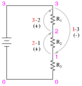
It is important to realize that the "loop" stepped around does not have to be the same path that current takes in the circuit, or even a legitimate current path at all. The loop in which we tally voltage drops can be any collection of points, so long as it begins and ends with the same point. For example, we may measure and add the voltages in the loop 1-2-3-1, and they will form a sum of zero as well:
Try stepping between any set of points, in any order, around your circuit and see for yourself that the algebraic sum always equals zero. This Law holds true no matter what the configuration of the circuit: series, parallel, series-parallel, or even an irreducible network.
Kirchhoff's Voltage Law is a powerful concept, allowing us to predict the magnitude and polarity of voltages in a circuit by developing mathematical equations for analysis based on the truth of all voltages in a loop adding up to zero. This experiment is intended to give empirical evidence for and a deep understanding of Kirchhoff's Voltage Law as a general principle.
COMPUTER SIMULATION
Netlist (make a text file containing the following text, verbatim):
Voltage divider
v1 3 0
r1 3 2 5k
r2 2 1 3k
r3 1 0 2k
.dc v1 6 6 1
* Voltages around 0-1-2-3-0 loop algebraically add to zero:
.print dc v(1,0) v(2,1) v(3,2) v(0,3)
* Voltages around 1-2-3-1 loop algebraically add to zero:
.print dc v(2,1) v(3,2) v(1,3)
.end
This computer simulation is based on the point numbers shown in the previous diagrams for illustrating Kirchhoff's Voltage Law (points 0 through 3). Resistor values were chosen to provide 50%, 30%, and 20% proportions of total voltage across R1, R2, and R3, respectively. Feel free to modify the voltage source value (in the ".dc" line, shown here as 6 volts), and/or the resistor values.
When run, SPICE will print a line of text containing four voltage figures, then another line of text containing three voltage figures, along with lots of other text lines describing the analysis process. Add the voltage figures in each line to see that the sum is zero.
PARTS AND MATERIALS
CROSS-REFERENCES
Lessons In Electric Circuits, Volume 1, chapter 6: "Divider Circuits and Kirchhoff's Laws"
LEARNING OBJECTIVES
SCHEMATIC DIAGRAM
ILLUSTRATION
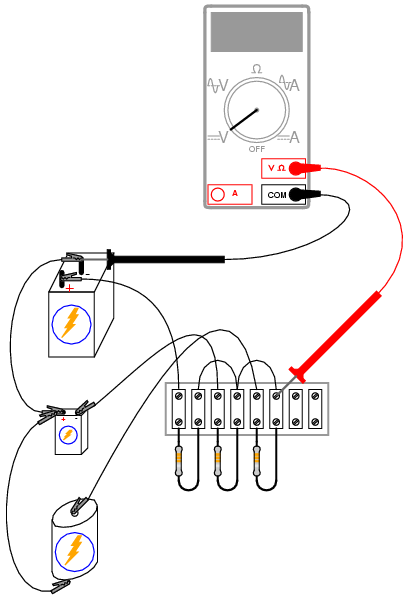
Normally, it is considered improper to secure more than two wires under a single terminal strip screw. In this illustration, I show three wires joining at the top screw of the rightmost lug used on this strip. This is done for the ease of proving a concept (of current summing at a circuit node), and does not represent professional assembly technique.
The non-professional nature of the "free-form" construction method merits no further comment.
INSTRUCTIONS
Once again, I show different methods of constructing the same circuit: breadboard, terminal strip, and "free-form." Experiment with all these construction formats and become familiar with their respective advantages and disadvantages.
Select three resistors from your resistor assortment and measure the resistance of each one with an ohmmeter. Note these resistance values with pen and paper, for reference in your circuit calculations.
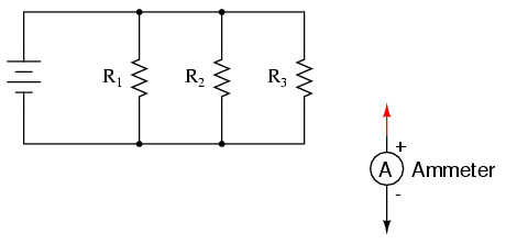
Connect the three resistors in parallel to and each other, and with the 6-volt battery, as shown in the illustrations. Measure battery voltage with a voltmeter after the resistors have been connected to it, noting this voltage figure on paper as well. It is advisable to measure battery voltage while it's powering the resistor circuit because this voltage may differ slightly from a no-load condition.
Measure voltage across each of the three resistors. What do you notice? In a series circuit, current is equal through all components at any given time. In a parallel circuit, voltage is the common variable between all components.
Use Ohm's Law (I=E/R) to calculate current through each resistor, then verify this calculated value by measuring current with a digital ammeter. Place the red probe of the ammeter at the point where the positive (+) ends of the resistors connect to each other and lift one resistor wire at a time, connecting the meter's black probe to the lifted wire. In this manner, measure each resistor current, noting both the magnitude of the current and the polarity. In these illustrations, I show an ammeter used to measure the current through R1:
Measure current for each of the three resistors, comparing with the current figures calculated previously. With the digital ammeter connected as shown, all three indications should be positive, not negative.
Now, measure total circuit current, keeping the ammeter's red probe on the same point of the circuit, but disconnecting the wire leading to the positive (+) side of the battery and touching the black probe to it:
Note both the magnitude and the sign of the current as indicated by the ammeter. Add this figure (algebraically) to the three resistor currents. What do you notice about the result that is similar to the Kirchhoff's Voltage Law experiment? Kirchhoff's Current Law is to currents "summing" at a point (node) in a circuit, just as Kirchhoff's Voltage Law is to voltages adding in a series loop: in both cases, the algebraic sum is equal to zero.
This Law is also very useful in the mathematical analysis of circuits. Along with Kirchhoff's Voltage Law, it allows us to generate equations describing several variables in a circuit, which may then be solved using a variety of mathematical techniques.
Now consider the four current measurements as all positive numbers: the first three representing the current through each resistor, and the fourth representing total circuit current as a positive sum of the three "branch" currents. Each resistor (branch) current is a fraction, or percentage, of the total current. This is why a parallel resistor circuit is often called a current divider.
Disconnect the battery from the rest of the circuit, and measure resistance across the parallel resistors. You may read total resistance across any of the individual resistors' terminals and obtain the same indication: it will be a value less than any of the individual resistor values. This is often surprising to new students of electricity, that you read the exact same (total) resistance figure when connecting an ohmmeter across any one of a set of parallel-connected resistors. It makes sense, though, if you consider the points in a parallel circuit in terms of electrical commonality. All parallel components are connected between two sets of electrically common points. Since the meter cannot distinguish between points common to each other by way of direct connection, to read resistance across one resistor is to read the resistance of them all. The same is true for voltage, which is why battery voltage could be read across any one of the resistors as easily as it could be read across the battery terminals directly.
If you divide the battery voltage (previously measured) by this total resistance figure, you should obtain a figure for total current (I=E/R) closely matching the measured figure.
The ratio of resistor current to total current is the same as the ratio of total resistance to individual resistance. For example, if a 10 kΩ resistor is part of a current divider circuit with a total resistance of 1 kΩ, that resistor will conduct 1/10 of the total current, whatever value that current total happens to be.
COMPUTER SIMULATION
Schematic with SPICE node numbers:
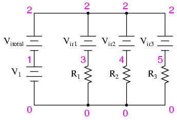
Ammeters in SPICE simulations are actually zero-voltage sources inserted in the paths of electron flow. You will notice the voltage sources Vir1, Vir2, and Vir3 are set to 0 volts in the netlist. When electrons enter the negative side of one of these "dummy" batteries and out the positive, the battery's current indication will be a positive number. In other words, these 0-volt sources are to be regarded as ammeters with the red probe on the long-line side of the battery symbol and the black probe on the short-line side.
Netlist (make a text file containing the following text, verbatim):
Current divider
v1 1 0
r1 3 0 2k
r2 4 0 3k
r3 5 0 5k
vitotal 2 1 dc 0
vir1 2 3 dc 0
vir2 2 4 dc 0
vir3 2 5 dc 0
.dc v1 6 6 1
.print dc i(vitotal) i(vir1) i(vir2) i(vir3)
.end
When run, SPICE will print a line of text containing four current figures, the first current representing the total as a negative quantity, and the other three representing currents for resistors R1, R2, and R3. When algebraically added, the one negative figure and the three positive figures will form a sum of zero, as described by Kirchhoff's Current Law.
PARTS AND MATERIALS
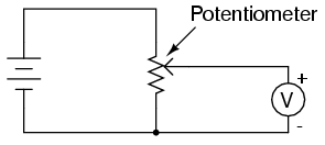
Potentiometers are variable voltage dividers with a shaft or slide control for setting the division ratio. They are manufactured in panel-mount as well as breadboard (printed-circuit board) mount versions. Any style of potentiometer will suffice for this experiment.
If you salvage a potentiometer from an old radio or other audio device, you will likely be getting what is called an audio taper potentiometer. These potentiometers exhibit a logarithmic relationship between division ratio and shaft position. By contrast, a linear potentiometer exhibits a direct correlation between shaft position and voltage division ratio. I highly recommend a linear potentiometer for this experiment, and for most experiments in general.
CROSS-REFERENCES
Lessons In Electric Circuits, Volume 1, chapter 6: "Divider Circuits and Kirchhoff's Laws"
LEARNING OBJECTIVES
SCHEMATIC DIAGRAM
ILLUSTRATION
INSTRUCTIONS
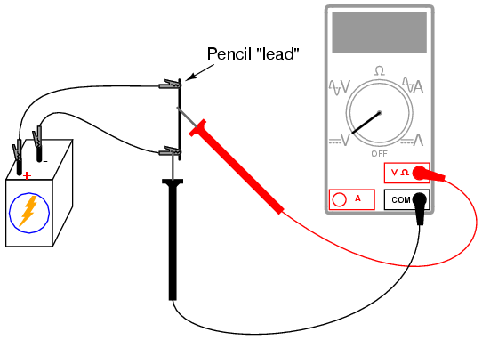
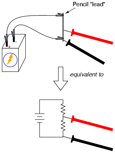
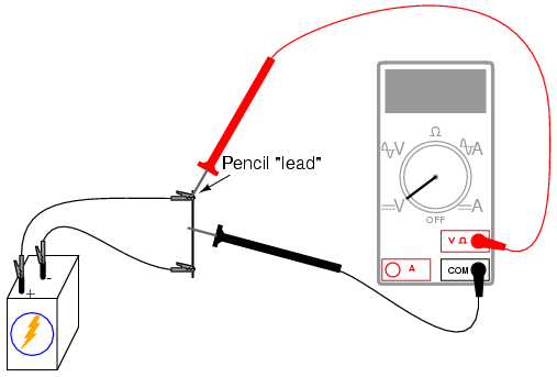
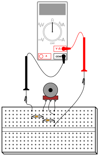
Begin this experiment with the pencil "lead" circuit. Pencils use a rod made of a graphite-clay mixture, not lead (the metal), to make black marks on paper. Graphite, being a mediocre electrical conductor, acts as a resistor connected across the battery by the two alligator-clip jumper wires. Connect the voltmeter as shown and touch the red test probe to the graphite rod. Move the red probe along the length of the rod and notice the voltmeter's indication change. What probe position gives the greatest voltage indication?
Essentially, the rod acts as a pair of resistors, the ratio between the two resistances established by the position of the red test probe along the rod's length:
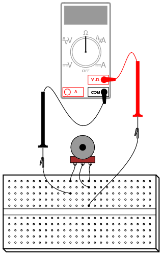
Now, change the voltmeter connection to the circuit so as to measure voltage across the "upper resistor" of the pencil lead, like this:
Move the black test probe position along the length of the rod, noting the voltmeter indication. Which position gives the greatest voltage drop for the meter to measure? Does this differ from the previous arrangement? Why?
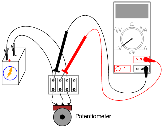
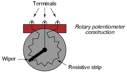
Manufactured potentiometers enclose a resistive strip inside a metal or plastic housing, and provide some kind of mechanism for moving a "wiper" across the length of that resistive strip. Here is an illustration of a rotary potentiometer's construction:
Some rotary potentiometers have a spiral resistive strip, and a wiper that moves axially as it rotates, so as to require multiple turns of the shaft to drive the wiper from one end of the potentiometer's range to the other. Multi-turn potentiometers are used in applications where precise setting is important.
Linear potentiometers also contain a resistive strip, the only difference being the wiper's direction of travel. Some linear potentiometers use a slide mechanism to move the wiper, while others a screw, to facilitate multiple-turn operation:
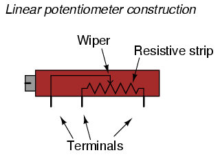
It should be noted that not all linear potentiometers have the same pin assignments. On some, the middle pin is the wiper.
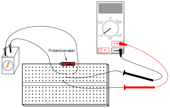
Set up a circuit using a manufactured potentiometer, not the "home-made" one made from a pencil lead. You may use any form of construction that is convenient.
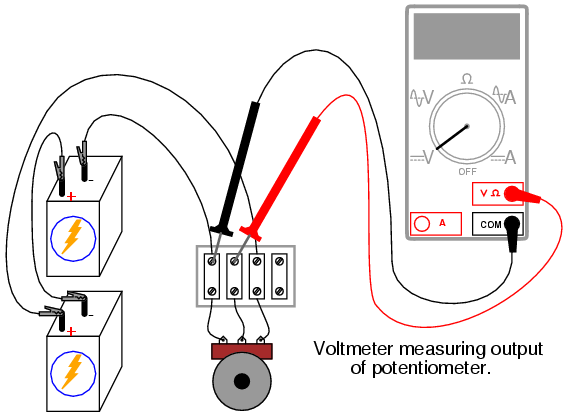
Measure battery voltage while powering the potentiometer, and make note of this voltage figure on paper. Measure voltage between the wiper and the potentiometer end connected to the negative (-) side of the battery. Adjust the potentiometer mechanism until the voltmeter registers exactly 1/3 of total voltage. For a 6-volt battery, this will be approximately 2 volts.
Now, connect two batteries in a series-aiding configuration, to provide approximately 12 volts across the potentiometer. Measure the total battery voltage, and then measure the voltage between the same two points on the potentiometer (wiper and negative side). Divide the potentiometer's measured output voltage by the measured total voltage. The quotient should be 1/3, the same voltage division ratio as was set previously:
PARTS AND MATERIALS
For this experiment, you will need a relatively low-value potentiometer, certainly not more than 5 kΩ.
CROSS-REFERENCES
Lessons In Electric Circuits, Volume 1, chapter 2: "Ohm's Law"
LEARNING OBJECTIVES
SCHEMATIC DIAGRAM
ILLUSTRATION

INSTRUCTIONS
Potentiometers find their most sophisticated application as voltage dividers, where shaft position determines a specific voltage division ratio. However, there are applications where we don't necessarily need a variable voltage divider, but merely a variable resistor: a two-terminal device. Technically, a variable resistor is known as a rheostat, but potentiometers can be made to function as rheostats quite easily.
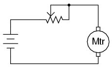
In its simplest configuration, a potentiometer may be used as a rheostat by simply using the wiper terminal and one of the other terminals, the third terminal left unconnected and unused:
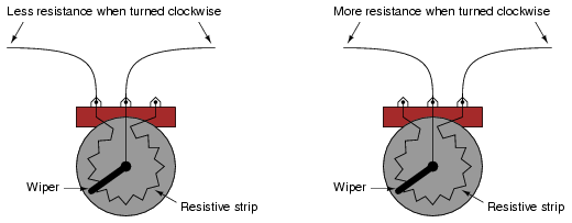
Moving the potentiometer control in the direction that brings the wiper closest to the other used terminal results in a lower resistance. The direction of motion required to increase or decrease resistance may be changed by using a different set of terminals:
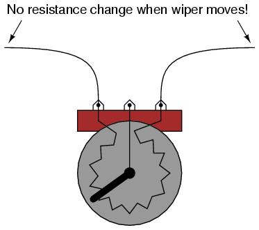
Be careful, though, that you don't use the two outer terminals, as this will result in no change in resistance as the potentiometer shaft is turned. In other words, it will no longer function as a variable resistance:
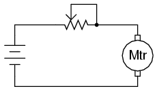
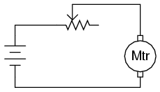
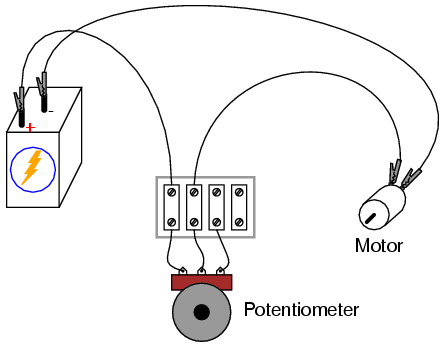
Build the circuit as shown in the schematic and illustration, using just two terminals on the potentiometer, and see how motor speed may be controlled by adjusting shaft position. Experiment with different terminal connections on the potentiometer, noting the changes in motor speed control. If your potentiometer has a high resistance (as measured between the two outer terminals), the motor might not move at all until the wiper is brought very close to the connected outer terminal.
As you can see, motor speed may be made variable using a series-connected rheostat to change total circuit resistance and limit total current. This simple method of motor speed control, however, is inefficient, as it results in substantial amounts of power being dissipated (wasted) by the rheostat. A much more efficient means of motor control relies on fast "pulsing" of power to the motor, using a high-speed switching device such as a transistor. A similar method of power control is used in household light "dimmer" switches. Unfortunately, these techniques are much too sophisticated to explore at this point in the experiments.
When a potentiometer is used as a rheostat, the "unused" terminal is often connected to the wiper terminal, like this:
At first, this seems rather pointless, as it has no impact on resistance control. You may verify this fact for yourself by inserting another wire in your circuit and comparing motor behavior before and after the change:
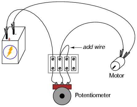
If the potentiometer is in good working order, this additional wire makes no difference whatsoever. However, if the wiper ever loses contact with the resistive strip inside the potentiometer, this connection ensures the circuit does not completely open: that there will still be a resistive path for current through the motor. In some applications, this may be an important. Old potentiometers tend to suffer from intermittent losses of contact between the wiper and the resistive strip, and if a circuit cannot tolerate the complete loss of continuity (infinite resistance) created by this condition, that "extra" wire provides a measure of protection by maintaining circuit continuity.
You may simulate such a wiper contact "failure" by disconnecting the potentiometer's middle terminal from the terminal strip, measuring voltage across the motor to ensure there is still power getting to it, however small:
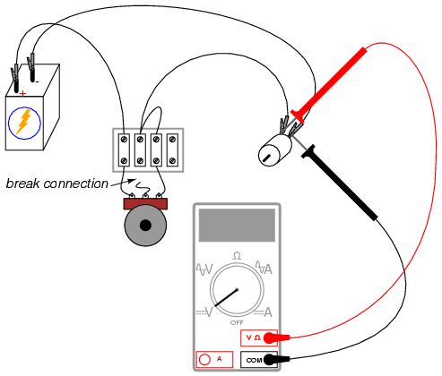
It would have been valid to measure circuit current instead of motor voltage to verify a completed circuit, but this is a safer method because it does not involve breaking the circuit to insert an ammeter in series. Whenever an ammeter is used, there is risk of causing a short circuit by connecting it across a substantial voltage source, possibly resulting in instrument damage or personal injury. Voltmeters lack this inherent safety risk, and so whenever a voltage measurement may be made instead of a current measurement to verify the same thing, it is the wiser choice.
PARTS AND MATERIALS
This is a project useful to those who want a precision potentiometer without spending a lot of money. Ordinarily, multi-turn potentiometers are used to obtain precise voltage division ratios, but a cheaper alternative exists using multiple, single-turn (sometimes called "3/4-turn") potentiometers connected together in a compound divider network.
Because this is a useful project, I recommend building it in permanent form using some form of project enclosure. Suppliers such as Radio Shack offer nice project boxes, but boxes purchased at a general hardware store are much less expensive, if a bit ugly. The ultimate in low cost for a new box are the plastic boxes sold as light switch and receptacle boxes for household electrical wiring.
"Banana" jacks allow for the temporary connection of test leads and jumper wires equipped with matching "banana" plug ends. Most multimeter test leads have this style of plug for insertion into the meter jacks. Banana plugs are so named because of their oblong appearance formed by spring steel strips, which maintain firm contact with the jack walls when inserted. Some banana jacks are called binding posts because they also allow plain wires to be firmly attached. Binding posts have screw-on sleeves that fit over a metal post. The sleeve is used as a nut to secure a wire wrapped around the post, or inserted through a perpendicular hole drilled through the post. A brief inspection of any binding post will clarify this verbal description.
CROSS-REFERENCES
Lessons In Electric Circuits, Volume 1, chapter 6: "Divider Circuits and Kirchhoff's Laws"
LEARNING OBJECTIVES
SCHEMATIC DIAGRAM
ILLUSTRATION
INSTRUCTIONS
It is essential that the connecting wires be soldered to the potentiometer terminals, not twisted or taped. Since potentiometer action is dependent on resistance, the resistance of all wiring connections must be carefully controlled to a bare minimum. Soldering ensures a condition of low resistance between joined conductors, and also provides very good mechanical strength for the connections.
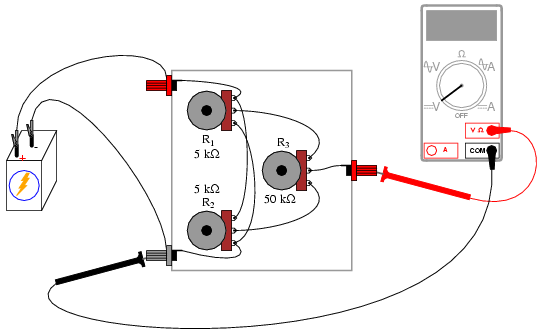
When the circuit is assembled, connect a 6-volt battery to the outer two binding posts. Connect a voltmeter between the "wiper" post and the battery's negative (-) terminal. This voltmeter will measure the "output" of the circuit.
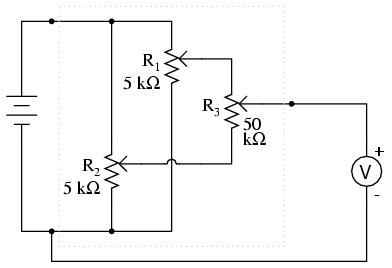
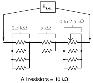
The circuit works on the principle of compressed range: the voltage output range of this circuit available by adjusting potentiometer R3 is restricted between the limits set by potentiometers R1 and R2. In other words, if R1 and R2 were set to output 5 volts and 3 volts, respectively, from a 6-volt battery, the range of output voltages obtainable by adjusting R3 would be restricted from 3 to 5 volts for the full rotation of that potentiometer. If only a single potentiometer were used instead of this three-potentiometer circuit, full rotation would produce an output voltage from 0 volts to full battery voltage. The "range compression" afforded by this circuit allows for more precise voltage adjustment than would be normally obtainable using a single potentiometer.
Operating this potentiometer network is more complex than using a single potentiometer. To begin, turn the R3 potentiometer fully clockwise, so that its wiper is in the full "up" position as referenced to the schematic diagram (electrically "closest" to R1's wiper terminal). Adjust potentiometer R1 until the upper voltage limit is reached, as indicated by the voltmeter.
Turn the R3 potentiometer fully counter-clockwise, so that its wiper is in the full "down" position as referenced to the schematic diagram (electrically "closest" to R2's wiper terminal). Adjust potentiometer R2 until the lower voltage limit is reached, as indicated by the voltmeter.
When either the R1 or the R2 potentiometer is adjusted, it interferes with the prior setting of the other. In other words, if R1 is initially adjusted to provide an upper voltage limit of 5.000 volts from a 6 volt battery, and then R2 is adjusted to provide some lower limit voltage different from what it was before, R1 will no longer be set to 5.000 volts.
To obtain precise upper and lower voltage limits, turn R3 fully clockwise to read and adjust the voltage of R1, then turn R3 fully counter-clockwise to read and adjust the voltage of R2, repeating as necessary.
Technically, this phenomenon of one adjustment affecting the other is known as interaction, and it is usually undesirable due to the extra effort required to set and re-set the adjustments. The reason that R1 and R2 were specified as 10 times less resistance than R3 is to minimize this effect. If all three potentiometers were of equal resistance value, the interaction between R1 and R2 would be more severe, though manageable with patience. Bear in mind that the upper and lower voltage limits need not be set precisely in order for this circuit to achieve its goal of increased precision. So long as R3's adjustment range is compressed to some lesser value than full battery voltage, we will enjoy greater precision than a single potentiometer could provide.
Once the upper and lower voltage limits have been set, potentiometer R3 may be adjusted to produce an output voltage anywhere between those limits.
PARTS AND MATERIALS
CROSS-REFERENCES
Lessons In Electric Circuits, Volume 1, chapter 5: "Series and Parallel Circuits"
Lessons In Electric Circuits, Volume 1, chapter 7: "Series-Parallel Combination Circuits"
Lessons In Electric Circuits, Volume 1, chapter 8: "DC Metering Circuits"
LEARNING OBJECTIVES
SCHEMATIC DIAGRAM
ILLUSTRATION
INSTRUCTIONS
This experiment explores the different resistance ranges obtainable from combining fixed-value resistors with a potentiometer connected as a rheostat. To begin, connect a 10 kΩ potentiometer as a rheostat with no other resistors connected. Adjusting the potentiometer through its full range of travel should result in a resistance that varies smoothly from 0 Ω to 10,000 Ω:
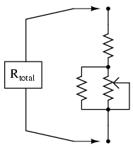
Suppose we wanted to elevate the lower end of this resistance range so that we had an adjustable range from 10 kΩ to 20 kΩ with a full sweep of the potentiometer's adjustment. This could be easily accomplished by adding a 10 kΩ resistor in series with the potentiometer. Add one to the circuit as shown and re-measure total resistance while adjusting the potentiometer:

A shift in the low end of an adjustment range is called a zero calibration, in metrological terms. With the addition of a series 10 kΩ resistor, the "zero point" was shifted upward by 10,000 Ω. The difference between high and low ends of a range -- called the span of the circuit -- has not changed, though: a range of 10 kΩ to 20 kΩ has the same 10,000 Ω span as a range of 0 Ω to 10 kΩ. If we wish to shift the span of this rheostat circuit as well, we must change the range of the potentiometer itself. We could replace the potentiometer with one of another value, or we could simulate a lower-value potentiometer by placing a resistor in parallel with it, diminishing its maximum obtainable resistance. This will decrease the span of the circuit from 10 kΩ to something less.
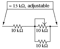
Add a 10 kΩ resistor in parallel with the potentiometer, to reduce the span to one-half of its former value: from 10 KΩ to 5 kΩ. Now the calibrated resistance range of this circuit will be 10 kΩ to 15 kΩ:
There is nothing we can do to increase the span of this rheostat circuit, short of replacing the potentiometer with another of greater total resistance. Adding resistors in parallel can only decrease the span. However, there is no such restriction with calibrating the zero point of this circuit, as it began at 0 Ω and may be made as great as we wish by adding resistance in series.
A multitude of resistance ranges may be obtained using only 10 KΩ fixed-value resistors, if we are creative with series-parallel combinations of them. For instance, we can create a range of 7.5 kΩ to 10 kΩ by building the following circuit:
Creating a custom resistance range from fixed-value resistors and a potentiometer is a very useful technique for producing precise resistances required for certain circuits, especially meter circuits. In many electrical instruments -- multimeters especially -- resistance is the determining factor for the instrument's range of measurement. If an instrument's internal resistance values are not precise, neither will its indications be. Finding a fixed-value resistor of just the right resistance for placement in an instrument circuit design is unlikely, so custom resistance "networks" may need to be built to provide the desired resistance. Having a potentiometer as part of the resistor network provides a means of correction if the network's resistance should "drift" from its original value. Designing the network for minimum span ensures that the potentiometer's effect will be small, so that precise adjustment is possible and so that accidental movement of its mechanism will not result in severe calibration errors.
Experiment with different resistor "networks" and note the effects on total resistance range.
PARTS AND MATERIALS
Iron wire may be obtained from a hardware store. If some cannot be found, aluminum wire also works.
CROSS-REFERENCES
Lessons In Electric Circuits, Volume 1, chapter 9: "Electrical Instrumentation Signals"
LEARNING OBJECTIVES
SCHEMATIC DIAGRAM

ILLUSTRATION
INSTRUCTIONS
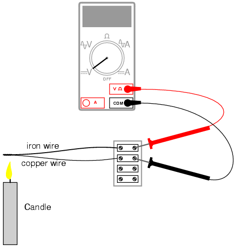
Twist one end of the iron wire together with one end of the copper wire. Connect the free ends of these wires to respective terminals on a terminal strip. Set your voltmeter to its most sensitive range and connect it to the terminals where the wires attach. The meter should indicate nearly zero voltage.
What you have just constructed is a thermocouple: a device which generates a small voltage proportional to the temperature difference between the tip and the meter connection points. When the tip is at a temperature equal to the terminal strip, there will be no voltage produced, and thus no indication seen on the voltmeter.
Light a candle and insert the twisted-wire tip into the flame. You should notice an indication on your voltmeter. Remove the thermocouple tip from the flame and let cool until the voltmeter indication is nearly zero again. Now, touch the thermocouple tip to an ice cube and note the voltage indicated by the meter. Is it a greater or lesser magnitude than the indication obtained with the flame? How does the polarity of this voltage compare with that generated by the flame?
After touching the thermocouple tip to the ice cube, warm it by holding it between your fingers. It may take a short while to reach body temperature, so be patient while observing the voltmeter's indication.
A thermocouple is an application of the Seebeck effect: the production of a small voltage proportional to a temperature gradient along the length of a wire. This voltage is dependent upon the magnitude of the temperature difference and the type of wire. Directly measuring the Seebeck voltage produced along a length of continuous wire from a temperature gradient is quite difficult, and so will not be attempted in this experiment.
Thermocouples, being made of two dissimilar metals joined at one end, produce a voltage proportional to the temperature of the junction. The temperature gradient along both wires resulting from a constant temperature at the junction produces different Seebeck voltages along those wires' lengths, because the wires are made of different metals. The resultant voltage between the two free wire ends is the difference between the two Seebeck voltages:
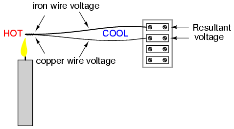
Thermocouples are widely used as temperature-sensing devices because the mathematical relationship between temperature difference and resultant voltage is both repeatable and fairly linear. By measuring voltage, it is possible to infer temperature. Different ranges of temperature measurement are possible by selecting different metal pairs to be joined together.
PARTS AND MATERIALS
The most important and expensive component in a meter is the movement: the actual needle-and-scale mechanism whose task it is to translate an electrical current into mechanical displacement where it may be visually interpreted. The ideal meter movement is physically large (for ease of viewing) and as sensitive as possible (requires minimal current to produce full-scale deflection of the needle). High-quality meter movements are expensive, but Radio Shack carries some of acceptable quality that are reasonably priced. The model recommended in the parts list is sold as a voltmeter with a 0-15 volt range, but is actually a milliammeter with a range ("multiplier") resistor included separately.
It may be cheaper to purchase an inexpensive analog meter and disassemble it for the meter movement alone. Although the thought of destroying a working multimeter in order to have parts to make your own may sound counter-productive, the goal here is learning, not meter function.
I cannot specify resistor values for this experiment, as these depend on the particular meter movement and measurement ranges chosen. Be sure to use high-precision fixed-value resistors rather than carbon-composition resistors. Even if you happen to find carbon-composition resistors of just the right value(s), those values will change or "drift" over time due to aging and temperature fluctuations. Of course, if you don't care about the long-term stability of this meter but are building it just for the learning experience, resistor precision matters little.
CROSS-REFERENCES
Lessons In Electric Circuits, Volume 1, chapter 8: "DC Metering Circuits"
LEARNING OBJECTIVES
SCHEMATIC DIAGRAM
ILLUSTRATION
INSTRUCTIONS
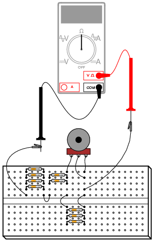
First, you need to determine the characteristics of your meter movement. Most important is to know the full scale deflection in milliamps or microamps. To determine this, connect the meter movement, a potentiometer, battery, and digital ammeter in series. Adjust the potentiometer until the meter movement is deflected exactly to full-scale. Read the ammeter's display to find the full-scale current value:
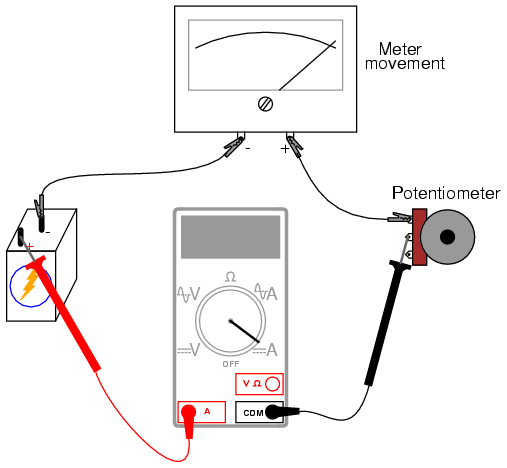
Be very careful not to apply too much current to the meter movement, as movements are very sensitive devices and easily damaged by overcurrent. Most meter movements have full-scale deflection current ratings of 1 mA or less, so choose a potentiometer value high enough to limit current appropriately, and begin testing with the potentiometer turned to maximum resistance. The lower the full-scale current rating of a movement, the more sensitive it is.
After determining the full-scale current rating of your meter movement, you must accurately measure its internal resistance. To do this, disconnect all components from the previous testing circuit and connect your digital ohmmeter across the meter movement terminals. Record this resistance figure along with the full-scale current figure obtained in the last procedure.
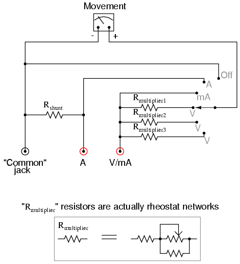
Perhaps the most challenging portion of this project is determining the proper range resistance values and implementing those values in the form of rheostat networks. The calculations are outlined in chapter 8 of volume 1 ("Metering Circuits"), but an example is given here. Suppose your meter movement had a full-scale rating of 1 mA and an internal resistance of 400 Ω. If we wanted to determine the necessary range resistance ("Rmultiplier") to give this movement a range of 0 to 15 volts, we would have to divide 15 volts (total applied voltage) by 1 mA (full-scale current) to obtain the total probe-to-probe resistance of the voltmeter (R=E/I). For this example, that total resistance is 15 kΩ. From this total resistance figure, we subtract the movement's internal resistance, leaving 14.6 kΩ for the range resistor value. A simple rheostat network to produce 14.6 kΩ (adjustable) would be a 10 kΩ potentiometer in parallel with a 10 kΩ fixed resistor, all in series with another 10 kΩ fixed resistor:
One position of the selector switch directly connects the meter movement between the black Common binding post and the red V/mA binding post. In this position, the meter is a sensitive ammeter with a range equal to the full-scale current rating of the meter movement. The far clockwise position of the switch disconnects the positive (+) terminal of the movement from either red binding post and shorts it directly to the negative (-) terminal. This protects the meter from electrical damage by isolating it from the red test probe, and it "dampens" the needle mechanism to further guard against mechanical shock.
The shunt resistor (Rshunt) necessary for a high-current ammeter function needs to be a low-resistance unit with a high power dissipation. You will definitely not be using any 1/4 watt resistors for this, unless you form a resistance network with several smaller resistors in parallel combination. If you plan on having an ammeter range in excess of 1 amp, I recommend using a thick piece of wire or even a skinny piece of sheet metal as the "resistor," suitably filed or notched to provide just the right amount of resistance.
To calibrate a home-made shunt resistor, you will need to connect the your multimeter assembly to a calibrated source of high current, or a high-current source in series with a digital ammeter for reference. Use a small metal file to shave off shunt wire thickness or to notch the sheet metal strip in small, careful amounts. The resistance of your shunt will increase with every stroke of the file, causing the meter movement to deflect more strongly. Remember that you can always approach the exact value in slower and slower steps (file strokes), but you cannot go "backward" and decrease the shunt resistance!
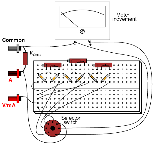
Build the multimeter circuit on a breadboard first while determining proper range resistance values, and perform all calibration adjustments there. For final construction, solder the components on to a printed-circuit board. Radio Shack sells printed circuit boards that have the same layout as a breadboard, for convenience (catalog # 276-170). Feel free to alter the component layout from what is shown.
I strongly recommend that you mount the circuit board and all components in a sturdy box, so that the meter is durably finished. Despite the limitations of this multimeter (no resistance function, inability to measure alternating current, and lower precision than most purchased analog multimeters), it is an excellent project to assist learning fundamental instrument principles and circuit function. A far more accurate and versatile multimeter may be constructed using many of the same parts if an amplifier circuit is added to it, so save the parts and pieces for a later experiment!
PARTS AND MATERIALS
Regarding the headphones, the higher the "sensitivity" rating in decibels (dB), the better, but listening is believing: if you're serious about building a detector with maximum sensitivity for small electrical signals, you should try a few different headphone models at a high-quality audio store and "listen" for which ones produce an audible sound for the lowest volume setting on a radio or CD player. Beware, as you could spend hundreds of dollars on a pair of headphones to get the absolute best sensitivity! Take heart, though: I've used an old pair of Radio Shack "Realistic" brand headphones with perfectly adequate results, so you don't need to buy the best.
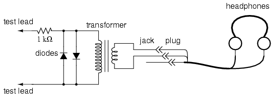
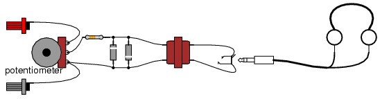
A transformer is a device normally used with alternating current ("AC") circuits, used to convert high-voltage AC power into low-voltage AC power, and for many other purposes. It is not important that you understand its intended function in this experiment, other than it makes the headphones become more sensitive to low-current electrical signals.
Normally, the transformer used in this type of application (audio speaker impedance matching) is called an "audio transformer," with its primary and secondary windings represented by impedance values (1000 Ω : 8 Ω) instead of voltages. An audio transformer will work, but I've found small step-down power transformers of 120/6 volt ratio to be perfectly adequate for the task, cheaper (especially when taken from an old thrift-store alarm clock radio), and far more rugged.
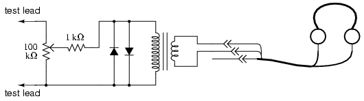
The tolerance (precision) rating for the 1 kΩ resistor is irrelevant. The 100 kΩ potentiometer is a recommended option for incorporation into this project, as it gives the user control over the loudness for any given signal. Even though an audio-taper potentiometer would be appropriate for this application, it is not necessary. A linear-taper potentiometer works quite well.
CROSS-REFERENCES
Lessons In Electric Circuits, Volume 1, chapter 8: "DC Metering Circuits"
Lessons In Electric Circuits, Volume 1, chapter 10: "DC Network Analysis" (in regard to the Maximum Power Transfer Theorem)
Lessons In Electric Circuits, Volume 2, chapter 9: "Transformers"
Lessons In Electric Circuits, Volume 2, chapter 12: "AC Metering Circuits"
LEARNING OBJECTIVES
SCHEMATIC DIAGRAM
ILLUSTRATION
INSTRUCTIONS
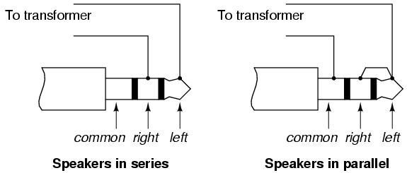
The headphones, most likely being stereo units (separate left and right speakers) will have a three-contact plug. You will be connecting to only two of those three contact points. If you only have a "mono" headphone set with a two-contact plug, just connect to those two contact points. You may either connect the two stereo speakers in series or in parallel. I've found the series connection to work best, that is, to produce the most sound from a small signal:
Solder all wire connections well. This detector system is extremely sensitive, and any loose wire connections in the circuit will add unwanted noise to the sounds produced by the measured voltage signal. The two diodes (arrow-like component symbols) connected in parallel with the transformer's primary winding, along with the series-connected 1 kΩ resistor, work together to prevent any more than about 0.7 volts from being dropped across the primary coil of the transformer. This does one thing and one thing only: limit the amount of sound the headphones can produce. The system will work without the diodes and resistor in place, but there will be no limit to sound volume in the circuit, and the resulting sound caused by accidently connecting the test leads across a substantial voltage source (like a battery) can be deafening!
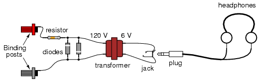
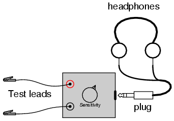
Binding posts provide points of connection for a pair of test probes with banana-style plugs, once the detector components are mounted inside a box. You may use ordinary multimeter probes, or make your own probes with alligator clips at the ends for secure connection to a circuit.
Detectors are intended to be used for balancing bridge measurement circuits, potentiometric (null-balance) voltmeter circuits, and detect extremely low-amplitude AC ("alternating current") signals in the audio frequency range. It is a valuable piece of test equipment, especially for the low-budget experimenter without an oscilloscope. It is also valuable in that it allows you to use a different bodily sense in interpreting the behavior of a circuit.
For connection across any non-trivial source of voltage (1 volt and greater), the detector's extremely high sensitivity should be attenuated. This may be accomplished by connecting a voltage divider to the "front" of the circuit:
SCHEMATIC DIAGRAM
ILLUSTRATION
Adjust the 100 kΩ voltage divider potentiometer to about mid-range when initially sensing a voltage signal of unknown magnitude. If the sound is too loud, turn the potentiometer down and try again. If too soft, turn it up and try again. The detector produces a "click" sound whenever the test leads make or break contact with the voltage source under test. With my cheap headphones, I've been able to detect currents of less than 1/10 of a microamp (< 0.1 µA).
A good demonstration of the detector's sensitivity is to touch both test leads to the end of your tongue, with the sensitivity adjustment set to maximum. The voltage produced by metal-to-electrolyte contact (called galvanic voltage) is very small, but enough to produce soft "clicking" sounds every time the leads make and break contact on the wet skin of your tongue.
Try unplugged the headphone plug from the jack (receptacle) and similarly touching it to the end of your tongue. You should still hear soft clicking sounds, but they will be much smaller in amplitude. Headphone speakers are "low impedance" devices: they require low voltage and "high" current to deliver substantial sound power. Impedance is a measure of opposition to any and all forms of electric current, including alternating current (AC). Resistance, by comparison, is a strictly measure of opposition to direct current (DC). Like resistance, impedance is measured in the unit of the Ohm (Ω), but it is symbolized in equations by the capital letter "Z" rather than the capital letter "R". We use the term "impedance" to describe the headphone's opposition to current because it is primarily AC signals that headphones are normally subjected to, not DC.
Most small signal sources have high internal impedances, some much higher than the nominal 8 Ω of the headphone speakers. This is a technical way of saying that they are incapable of supplying substantial amounts of current. As the Maximum Power Transfer Theorem predicts, maximum sound power will be delivered by the headphone speakers when their impedance is "matched" to the impedance of the voltage source. The transformer does this. The transformer also helps aid the detection of small DC signals by producing inductive "kickback" every time the test lead circuit is broken, thus "amplifying" the signal by magnetically storing up electrical energy and suddenly releasing it to the headphone speakers.
I recommend building this detector in a permanent fashion (mounting all components inside of a box, and providing nice test lead wires) so it may be easily used in the future. Constructed as such, it might look something like this:
PARTS AND MATERIALS
The potentiometer value is not critical: anything from 1 kΩ to 100 kΩ is acceptable. If you have built the "precision potentiometer" described earlier in this chapter, it is recommended that you use it in this experiment.
Likewise, the actual values of the resistors are not critical. In this particular experiment, the greater the value, the better the results. They need not be precisely equal value, either.
If you have not yet built the sensitive voltage detector, it is recommended that you build one before proceeding with this experiment! It is a very useful, yet simple, piece of test equipment that you should not be without. You can use a digital multimeter set to the "DC millivolt" (DC mV) range in lieu of a voltage detector, but the headphone-based voltage detector is more appropriate because it demonstrates how you can make precise voltage measurements without using expensive or advanced meter equipment. I recommend using your home-made multimeter for the same reason, although any voltmeter will suffice for this experiment.
CROSS-REFERENCES
Lessons In Electric Circuits, Volume 1, chapter 8: "DC Metering Circuits"
LEARNING OBJECTIVES
SCHEMATIC DIAGRAM
ILLUSTRATION
INSTRUCTIONS
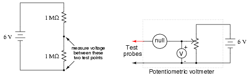
Build the two-resistor voltage divider circuit shown on the left of the schematic diagram and of the illustration. If the two high-value resistors are of equal value, the battery's voltage should be split in half, with approximately 3 volts dropped across each resistor.
Measure the battery voltage directly with a voltmeter, then measure each resistor's voltage drop. Do you notice anything unusual about the voltmeter's readings? Normally, series voltage drops add to equal the total applied voltage, but in this case you will notice a serious discrepancy. Is Kirchhoff's Voltage Law untrue? Is this an exception to one of the most fundamental laws of electric circuits? No! What is happening is this: when you connect a voltmeter across either resistor, the voltmeter itself alters the circuit so that the voltage is not the same as with no meter connected.
I like to use the analogy of an air pressure gauge used to check the pressure of a pneumatic tire. When a gauge is connected to the tire's fill valve, it releases some air out of the tire. This affects the pressure in the tire, and so the gauge reads a slightly lower pressure than what was in the tire before the gauge was connected. In other words, the act of measuring tire pressure alters the tire's pressure. Hopefully, though, there is so little air released from the tire during the act of measurement that the reduction in pressure is negligible. Voltmeters similarly impact the voltage they measure, by bypassing some current around the component whose voltage drop is being measured. This affects the voltage drop, but the effect is so slight that you usually don't notice it.
In this circuit, though, the effect is very pronounced. Why is this? Try replacing the two high-value resistors with two of 100 kΩ value each and repeat the experiment. Replace those resistors with two 10 KΩ units and repeat. What do you notice about the voltage readings with lower-value resistors? What does this tell you about voltmeter "impact" on a circuit in relation to that circuit's resistance? Replace any low-value resistors with the original, high-value (>= 1 MΩ) resistors before proceeding.
Try measuring voltage across the two high-value resistors -- one at a time -- with a digital voltmeter instead of an analog voltmeter. What do you notice about the digital meter's readings versus the analog meter's? Digital voltmeters typically have greater internal (probe-to-probe) resistance, meaning they draw less current than a comparable analog voltmeter when measuring the same voltage source. An ideal voltmeter would draw zero current from the circuit under test, and thus suffer no voltage "impact" problems.
If you happen to have two voltmeters, try this: connect one voltmeter across one resistor, and the other voltmeter across the other resistor. The voltage readings you get will add up to the total voltage this time, no matter what the resistor values are, even though they're different from the readings obtained from a single meter used twice. Unfortunately, though, it is unlikely that the voltage readings obtained this way are equal to the true voltage drops with no meters connected, and so it is not a practical solution to the problem.
Is there any way to make a "perfect" voltmeter: one that has infinite resistance and draws no current from the circuit under test? Modern laboratory voltmeters approach this goal by using semiconductor "amplifier" circuits, but this method is too technologically advanced for the student or hobbyist to duplicate. A much simpler and much older technique is called the potentiometric or null-balance method. This involves using an adjustable voltage source to "balance" the measured voltage. When the two voltages are equal, as indicated by a very sensitive null detector, the adjustable voltage source is measured with an ordinary voltmeter. Because the two voltage sources are equal to each other, measuring the adjustable source is the same as measuring across the test circuit, except that there is no "impact" error because the adjustable source provides any current needed by the voltmeter. Consequently, the circuit under test remains unaffected, allowing measurement of its true voltage drop.
Examine the following schematic to see how the potentiometric voltmeter method is implemented:
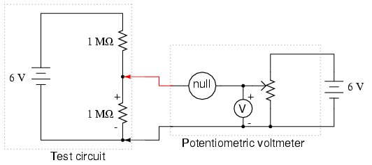
The circle symbol with the word "null" written inside represents the null detector. This can be any arbitrarily sensitive meter movement or voltage indicator. Its sole purpose in this circuit is to indicate when there is zero voltage: when the adjustable voltage source (potentiometer) is precisely equal to the voltage drop in the circuit under test. The more sensitive this null detector is, the more precisely the adjustable source may be adjusted to equal the voltage under test, and the more precisely that test voltage may be measured.
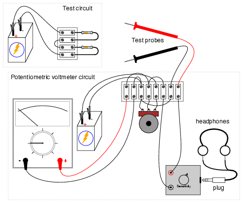
Build this circuit as shown in the illustration and test its operation measuring the voltage drop across one of the high-value resistors in the test circuit. It may be easier to use a regular multimeter as a null detector at first, until you become familiar with the process of adjusting the potentiometer for a "null" indication, then reading the voltmeter connected across the potentiometer.
If you are using the headphone-based voltage detector as your null meter, you will need to intermittently make and break contact with the circuit under test and listen for "clicking" sounds. Do this by firmly securing one of the test probes to the test circuit and momentarily touching the other test probe to the other point in the test circuit again and again, listening for sounds in the headphones indicating a difference of voltage between the test circuit and the potentiometer. Adjust the potentiometer until no clicking sounds can be heard from the headphones. This indicates a "null" or "balanced" condition, and you may read the voltmeter indication to see how much voltage is dropped across the test circuit resistor. Unfortunately, the headphone-based null detector provides no indication of whether the potentiometer voltage is greater than, or less than the test circuit voltage, so you will have to listen for decreasing "click" intensity while turning the potentiometer to determine if you need to adjust the voltage higher or lower.
You may find that a single-turn ("3/4 turn") potentiometer is too coarse of an adjustment device to accurately "null" the measurement circuit. A multi-turn potentiometer may be used instead of the single-turn unit for greater adjustment precision, or the "precision potentiometer" circuit described in an earlier experiment may be used.
Prior to the advent of amplified voltmeter technology, the potentiometric method was the only method for making highly accurate voltage measurements. Even now, electrical standards laboratories make use of this technique along with the latest meter technology to minimize meter "impact" errors and maximize measurement accuracy. Although the potentiometric method requires more skill to use than simply connecting a modern digital voltmeter across a component, and is considered obsolete for all but the most precise measurement applications, it is still a valuable learning process for the new student of electronics, and a useful technique for the hobbyist who may lack expensive instrumentation in their home laboratory.
COMPUTER SIMULATION
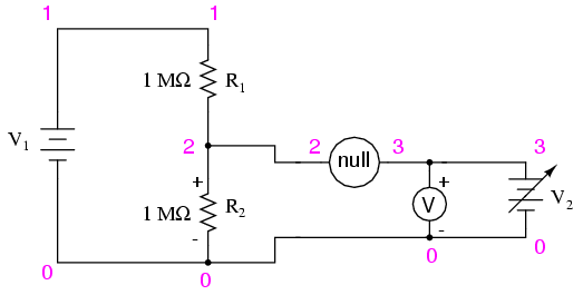
Schematic with SPICE node numbers:
Netlist (make a text file containing the following text, verbatim):
Potentiometric voltmeter
v1 1 0 dc 6
v2 3 0
r1 1 2 1meg
r2 2 0 1meg
rnull 2 3 10k
rmeter 3 0 50k
.dc v2 0 6 0.5
.print dc v(2,0) v(2,3) v(3,0)
.end
This SPICE simulation shows the actual voltage across R2 of the test circuit, the null detector's voltage, and the voltage across the adjustable voltage source, as that source is adjusted from 0 volts to 6 volts in 0.5 volt steps. In the output of this simulation, you will notice that the voltage across R2 is impacted significantly when the measurement circuit is unbalanced, returning to its true voltage only when there is practically zero voltage across the null detector. At that point, of course, the adjustable voltage source is at a value of 3.000 volts: precisely equal to the (unaffected) test circuit voltage drop.
What is the lesson to be learned from this simulation? That a potentiometric voltmeter avoids impacting the test circuit only when it is in a condition of perfect balance ("null") with the test circuit!
PARTS AND MATERIALS
It would be ideal in this experiment to have two meters: one voltmeter and one ammeter. For experimenters on a budget, this may not be possible. Whatever ammeter is used should be capable measuring at least a few amps of current. A 6-volt "lantern" battery essentially short-circuited by a long piece of wire may produce currents of this magnitude, and your ammeter needs to be capable of measuring it without blowing a fuse or sustaining other damage. Make sure the highest current range on the meter is at least 5 amps!
CROSS-REFERENCES
Lessons In Electric Circuits, Volume 1, chapter 8: "DC Metering Circuits"
LEARNING OBJECTIVES
SCHEMATIC DIAGRAM
ILLUSTRATION
INSTRUCTIONS
Although this experiment is best performed with two meters, and indeed is shown as such in the schematic diagram and illustration, one multimeter is sufficient.
Most ohmmeters operate on the principle of applying a small voltage across an unknown resistance (Runknown) and inferring resistance from the amount of current drawn by it. Except in special cases such as the megger, both the voltage and current quantities employed by the meter are quite small.
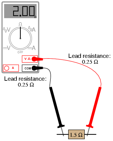
This presents a problem for measurement of low resistances, as a low resistance specimen may be of much smaller resistance value than the meter circuitry itself. Imagine trying to measure the diameter of a cotton thread with a yardstick, or measuring the weight of a coin with a scale built for weighing freight trucks, and you will appreciate the problem at hand.
One of the many sources of error in measuring small resistances with an ordinary ohmmeter is the resistance of the ohmmeter's own test leads. Being part of the measurement circuit, the test leads may contain more resistance than the resistance of the test specimen, incurring significant measurement error by their presence:
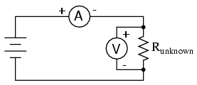
One solution is called the Kelvin, or 4-wire, resistance measurement method. It involves the use of an ammeter and voltmeter, determining specimen resistance by Ohm's Law calculation. A current is passed through the unknown resistance and measured. The voltage dropped across the resistance is measured by the voltmeter, and resistance calculated using Ohm's Law (R=E/I). Very small resistances may be measured easily by using large current, providing a more easily measured voltage drop from which to infer resistance than if a small current were used.
Because only the voltage dropped by the unknown resistance is factored into the calculation -- not the voltage dropped across the ammeter's test leads or any other connecting wires carrying the main current -- errors otherwise caused by these stray resistances are completely eliminated.
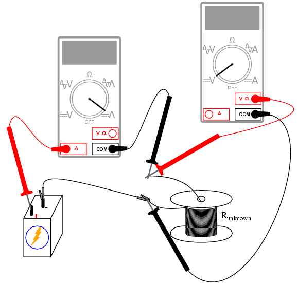
First, select a suitably low resistance specimen to use in this experiment. I suggest the electromagnet coil specified in the last chapter, or a spool of wire where both ends may be accessed. Connect a 6-volt battery to this specimen, with an ammeter connected in series. WARNING: the ammeter used should be capable of measuring at least 5 amps of current, so that it will not be damaged by the (possibly) high current generated in this near-short circuit condition. If you have a second meter, use it to measure voltage across the specimen's connection points, as shown in the illustration, and record both meters' indications.
If you have only one meter, use it to measure current first, recording its indication as quickly as possible, then immediately opening (breaking) the circuit. Switch the meter to its voltage mode, connect it across the specimen's connection points, and re-connect the battery, quickly noting the voltage indication. You don't want to leave the battery connected to the specimen for any longer than necessary for obtaining meter measurements, as it will begin to rapidly discharge due to the high circuit current, thus compromising measurement accuracy when the meter is re-configured and the circuit closed once more for the next measurement. When two meters are used, this is not as significant an issue, because the current and voltage indications may be recorded simultaneously.
Take the voltage measurement and divide it by the current measurement. The quotient will be equal to the specimen's resistance in ohms.
PARTS AND MATERIALS
When selecting resistors, measure each one with an ohmmeter and choose three that are the closest in value to each other. Precision is very important for this experiment!
CROSS-REFERENCES
Lessons In Electric Circuits, Volume 1, chapter 10: "DC Network Analysis"
LEARNING OBJECTIVES
SCHEMATIC DIAGRAM
ILLUSTRATION
INSTRUCTIONS
This deceptively crude circuit performs the function of mathematically averaging three voltage signals together, and so fulfills a specialized computational role. In other words, it is a computer that can only do one mathematical operation: averaging three quantities together.
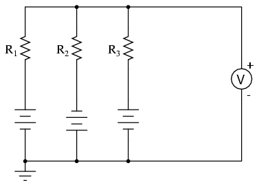
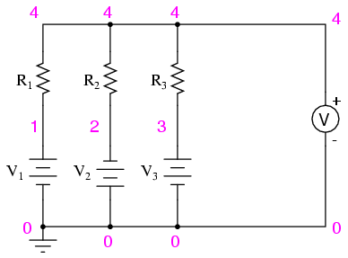
Build this circuit as shown and measure all battery voltages with a voltmeter. Write these voltage figures on paper and average them together (E1 + E2 + E3, divided by three). When you measure each battery voltage, keep the black test probe connected to the "ground" point (the side of the battery directly joined to the other batteries by jumper wires), and touch the red probe to the other battery terminal. Polarity is important here! You will notice one battery in the schematic diagram connected "backward" to the other two, negative side "up." This battery's voltage should read as a negative quantity when measured by a properly connected digital meter, the other batteries measuring positive.
When the voltmeter is connected to the circuit at the point shown in the schematic and illustrations, it should register the algebraic average of the three batteries' voltages. If the resistor values are chosen to match each other very closely, the "output" voltage of this circuit should match the calculated average very closely as well.
If one battery is disconnected, the output voltage will equal the average voltage of the remaining batteries. If the jumper wires formerly connecting the removed battery to the averager circuit are connected to each other, the circuit will average the two remaining voltages together with 0 volts, producing a smaller output signal:
The sheer simplicity of this circuit deters most people from calling it a "computer," but it undeniably performs the mathematical function of averaging. Not only does it perform this function, but it performs it much faster than any modern digital computer can! Digital computers, such as personal computers (PCs) and pushbutton calculators, perform mathematical operations in a series of discrete steps. Analog computers perform calculations in continuous fashion, exploiting Ohm's and Kirchhoff's Laws for an arithmetic purpose, the "answer" computed as fast as voltage propagates through the circuit (ideally, at the speed of light!).
With the addition of circuits called amplifiers, voltage signals in analog computer networks may be boosted and re-used in other networks to perform a wide variety of mathematical functions. Such analog computers excel at performing the calculus operations of numerical differentiation and integration, and as such may be used to simulate the behavior of complex mechanical, electrical, and even chemical systems. At one time, analog computers were the ultimate tool for engineering research, but since then have been largely supplanted by digital computer technology. Digital computers enjoy the advantage of performing mathematical operations with much better precision than analog computers, albeit at much slower theoretical speeds.
COMPUTER SIMULATION
Schematic with SPICE node numbers:
Netlist (make a text file containing the following text, verbatim):
Voltage averager
v1 1 0
v2 0 2 dc 9
v3 3 0 dc 1.5
r1 1 4 10k
r2 2 4 10k
r3 3 4 10k
.dc v1 6 6 1
.print dc v(4,0)
.end
With this SPICE netlist, we can force a digital computer to simulate and analog computer, which averages three numbers together. Obviously, we aren't doing this for the practical task of averaging numbers, but rather to learn more about circuits and more about computer simulation of circuits!
PARTS AND MATERIALS
The basic experiment is based on the use of a potato, but many fruits and vegetables work as potential batteries!
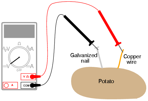
For the zinc electrode, a large galvanized nail works well. Nails with a thick, rough zinc texture are preferable to galvanized nails that are smooth.
CROSS-REFERENCES
Lessons In Electric Circuits, Volume 1, chapter 11: "Batteries and Power Systems"
LEARNING OBJECTIVES
ILLUSTRATION
INSTRUCTIONS
Push both the nail and the wire deep into the potato. Measure voltage output by the potato battery with a voltmeter. Now, wasn't that easy?
Seriously, though, experiment with different metals, electrode depths, and electrode spacings to obtain the greatest voltage possible from the potato. Try other vegetables or fruits and compare voltage output with the same electrode metals.
It can be difficult to power a load with a single "potato" battery, so don't expect to light up an incandescent lamp or power a hobby motor or do anything like that. Even if the voltage output is adequate, a potato battery has a fairly high internal resistance which causes its voltage to "sag" badly under even a light load. With multiple potato batteries connected in series, parallel, or series-parallel arrangement, though, it is possible to obtain enough voltage and current capacity to power a small load.
PARTS AND MATERIALS
Large-value capacitors are required for this experiment to produce time constants slow enough to track with a voltmeter and stopwatch. Be warned that most large capacitors are of the "electrolytic" type, and they are polarity sensitive! One terminal of each capacitor should be marked with a definite polarity sign. Usually capacitors of the size specified have a negative (-) marking or series of negative markings pointing toward the negative terminal. Very large capacitors are often polarity-labeled by a positive (+) marking next to one terminal. Failure to heed proper polarity will almost surely result in capacitor failure, even with a source voltage as low as 6 volts. When electrolytic capacitors fail, they typically explode, spewing caustic chemicals and emitting foul odors. Please, try to avoid this!
I recommend a household light switch for the "SPST toggle switch" specified in the parts list.
CROSS-REFERENCES
Lessons In Electric Circuits, Volume 1, chapter 13: "Capacitors"
Lessons In Electric Circuits, Volume 1, chapter 16: "RC and L/R Time Constants"
LEARNING OBJECTIVES
SCHEMATIC DIAGRAM
ILLUSTRATION
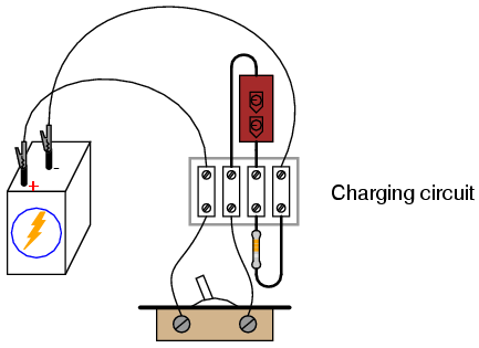
INSTRUCTIONS
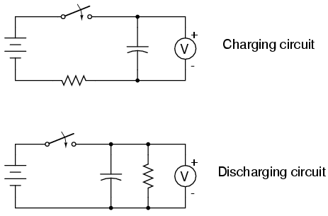
Build the "charging" circuit and measure voltage across the capacitor when the switch is closed. Notice how it increases slowly over time, rather than suddenly as would be the case with a resistor. You can "reset" the capacitor back to a voltage of zero by shorting across its terminals with a piece of wire.
The "time constant" (τ) of a resistor capacitor circuit is calculated by taking the circuit resistance and multiplying it by the circuit capacitance. For a 1 kΩ resistor and a 1000 µF capacitor, the time constant should be 1 second. This is the amount of time it takes for the capacitor voltage to increase approximately 63.2% from its present value to its final value: the voltage of the battery.
It is educational to plot the voltage of a charging capacitor over time on a sheet of graph paper, to see how the inverse exponential curve develops. In order to plot the action of this circuit, though, we must find a way of slowing it down. A one-second time constant doesn't provide much time to take voltmeter readings!
We can increase this circuit's time constant two different ways: changing the total circuit resistance, and/or changing the total circuit capacitance. Given a pair of identical resistors and a pair of identical capacitors, experiment with various series and parallel combinations to obtain the slowest charging action. You should already know by now how multiple resistors need to be connected to form a greater total resistance, but what about capacitors? This circuit will demonstrate to you how capacitance changes with series and parallel capacitor connections. Just be sure that you insert the capacitor(s) in the proper direction: with the ends labeled negative (-) electrically "closest" to the battery's negative terminal!
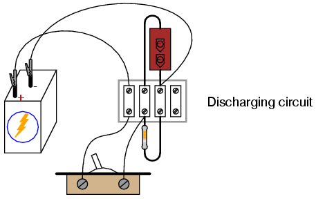
The discharging circuit provides the same kind of changing capacitor voltage, except this time the voltage jumps to full battery voltage when the switch closes and slowly falls when the switch is opened. Experiment once again with different combinations of resistors and capacitors, making sure as always that the capacitor's polarity is correct.
COMPUTER SIMULATION
Schematic with SPICE node numbers:
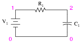
Netlist (make a text file containing the following text, verbatim):
Capacitor charging circuit
v1 1 0 dc 6
r1 1 2 1k
c1 2 0 1000u ic=0
.tran 0.1 5 uic
.plot tran v(2,0)
.end
PARTS AND MATERIALS
The potentiometer value is not especially critical, although lower-resistance units will, in theory, work better for this experiment than high-resistance units. I've used a 10 kΩ potentiometer for this circuit with excellent results.
CROSS-REFERENCES
Lessons In Electric Circuits, Volume 1, chapter 13: "Capacitors"
LEARNING OBJECTIVES
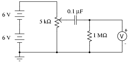
SCHEMATIC DIAGRAM
ILLUSTRATION
INSTRUCTIONS
Measure voltage between the potentiometer's wiper terminal and the "ground" point shown in the schematic diagram (the negative terminal of the lower 6-volt battery). This is the input voltage for the circuit, and you can see how it smoothly varies between zero and 12 volts as the potentiometer control is turned full-range. Since the potentiometer is used here as a voltage divider, this behavior should be unsurprising to you.
Now, measure voltage across the 1 MΩ resistor while moving the potentiometer control. A digital voltmeter is highly recommended, and I advise setting it to a very sensitive (millivolt) range to obtain the strongest indications. What does the voltmeter indicate while the potentiometer is not being moved? Turn the potentiometer slowly clockwise and note the voltmeter's indication. Turn the potentiometer slowly counter-clockwise and note the voltmeter's indication. What difference do you see between the two different directions of potentiometer control motion?
Try moving the potentiometer in such a way that the voltmeter gives a steady, small indication. What kind of potentiometer motion provides the steadiest voltage across the 1 MΩ resistor?
In calculus, a function representing the rate of change of one variable as compared to another is called the derivative. This simple circuit illustrates the concept of the derivative by producing an output voltage proportional to the input voltage's rate of change over time. Because this circuit performs the calculus function of differentiation with respect to time (outputting the time-derivative of an incoming signal), it is called a differentiator circuit.
Like the averager circuit shown earlier in this chapter, the differentiator circuit is a kind of analog computer. Differentiation is a far more complex mathematical function than averaging, especially when implemented in a digital computer, so this circuit is an excellent demonstration of the elegance of analog circuitry in performing mathematical computations.
More accurate differentiator circuits may be built by combining resistor-capacitor networks with electronic amplifier circuits. For more detail on computational circuitry, go to the "Analog Integrated Circuits" chapter in this Experiments volume.
Lessons In Electric Circuits copyright (C) 2002-2007 Tony R. Kuphaldt, under the terms and conditions of the Design Science License.