Copyright Michael Karbo and ELI Aps., Denmark, Europe.
Chapter 45. System software. A small glossary
We have now examined most of the PCs architecture, from CPU and RAM, to expansion buses, to the hard disk. We still need to look at the motherboards built-in system software.There is software stored on every motherboard. The ROM circuits contain important system routines which help to startup the PC and which hold everything together. The following chapters provide a brief introduction to these topics:
The guide concludes with a glossary.
PC startup
When you switch on the power to your PC, a lot of things happen. You here the noise of the various cooling fans, and shortly afterwards, text starts to scroll up onto the screen. It is the system software which is doing this work.
Remember that the PC cannot do anything unless it receives instructions. Instructions are fragments of programs which are loaded into the CPU, and the CPU starts by executing the system software which is stored on the motherboard. Later, once the PC is up and running, the operating system can fetch instructions (programs) itself from the hard disk; but during startup, the CPU is fed instructions from the ROM code in the motherboard.
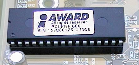 Figure 233. A ROM circuit containing Award
BIOS (typically 1 or 2 MB of data).
Figure 233. A ROM circuit containing Award
BIOS (typically 1 or 2 MB of data).
That is, the startup programs are stored in ROM circuits. ROM stands for Read Only Memory. These circuits contain data, which can normally only be read. Thus the PC is born at the manufacturer with system software stored in its hardware.
On newer motherboards, however, Flash ROM is used (so-called EEPROM circuits). With these, the data can be changed by the user (BIOS updates). For convenience, these circuits are still called BIOS ROM.
BIOS is important system software, because it is only after these programs have been loaded and executed that the PCs operating system can be loaded from the hard disk (or alternatively, from a diskette or another drive). This is called the boot process.
Checking the hardware
If POST encounters a fault in the machine, the program will write a message on the screen. If the screen has not yet been made ready, or if the fault is, for example, linked to the video card, the program will normally emit beeps using the PC speaker. The pattern of bleeps and beeps varies for the different BIOS manufacturers, but the pattern indicates where the fault is located. For example, 8 beeps from a BIOS from AMI can mean a fault in the graphics system, while a constant series of short beeps indicates a fault in the RAM when using BIOS from Award. Some motherboards have built in LEDs which can also signal faults (you can actually see these in Fig. 30. The fault messages are always explained in the motherboard manual.
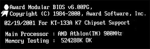
When POST has finished executing, you normally hear a single beep from the speaker, and startup continues. Next the BIOS is loaded for the video card. This leads to the first text on the screen, which is normally the name of the BIOS supplier and the program version.
The startup program is now in the process of checking the various hardware, and generally bringing the machine to life. You can make contact with the Setup program at this time, for example by pressing the Delete key once. After this you will see that the RAM is being counted. You can also read which CPU is in the machine. Any error messages (e.g. if the hard disk is not connected properly) can now be seen on the screen.
Try to follow the startup process yourself when you switch on your PC. You can stop the process by pressing the Pause key, so that you have time to read the messages. Below you can see the startup messages for a PC with Award BIOS, which has found 512 MB of RAM.
The startup program installs the other system devices, such as floppy disk and ATA drives, and locates the logical devices (such as COM, LPT, etc.). The PCI bus is scanned for devices.
CMOS and Setup
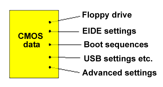
The startup program needs information about the PCs hardware. However, some of this system information has to be manually entered. This includes things like whether a floppy disk drive is installed, and the actual time and date, etc. Fortunately we dont have to type in this information every time we start the PC. It is done by the manufacturer, and the information is stored in a small CMOS chip.
CMOS is a special type of RAM, which excels at using very little power. The chip is used as a storage area for the small database of hardware information. The database is necessary for the startup programs, which, for example, use it as a list of the hardware which has to be checked. See also the discussion of ESCD, which is included in the CMOS storage. This is a store containing information about the PCs Plug and Play compatible devices.
You can correct the settings in the CMOS storage yourself. You might need to do this, for example, if you install a new hard disk. Thats why we have access to the CMOS via the Setup program, which is also stored in the motherboards ROM circuits. Setup can be activated during startup by pressing a special key (e.g. Delete).
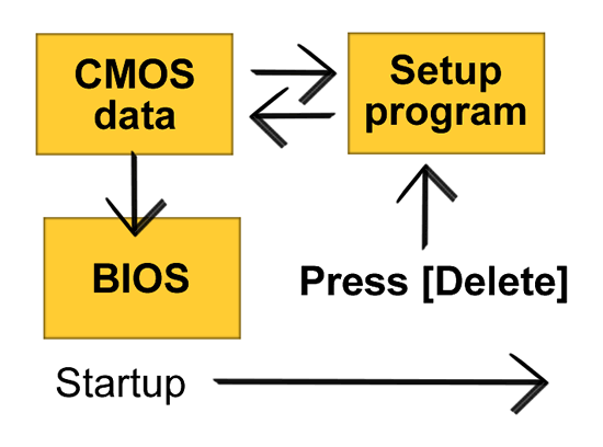
Figure 235. The Setup program is used to change the settings in the CMOS storage.
Chapter XX. A quick look at Setup
If you want to look at the facilities of the Setup program, you have to activate it while the startup programs are scrolling over the screen.
The Setup program can look a bit different, from one PC to another. Below is the opening menu from my PC:
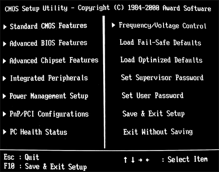
There are many options, which in this example have been divided into 14 different submenus. I wont go through the whole system; as most of it you will never use anyway.
But lets take a look at some of the options the various menus offer, including features, setup and configuration. Even though you wont need to change these settings on your own PC, they provide a good picture of how the Setup program can be used to adjust and actually program the motherboard in various ways,
Standard CMOS Features
This menu is one of the most fundamental of them all. Here you can change the date and time. Floppy disk drives are so unintelligent that the test program cannot check whether a floppy drive is installed or not. This must therefore be specified.
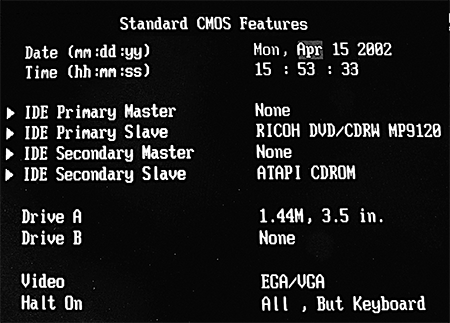
You can also set which ATA channels are in use. In Fig. 237 I have chosen the setting None, for the two unused ATA channels. This allows a slightly faster startup, since the program doesnt have to search for devices which dont exist.
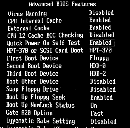
Advanced BIOS Features
Here you can set which device should be used to boot from. It can be the hard disk or the floppy disk, and if you have several built-in hard disk controllers (ATA, RAID or SCSI), you specify which of them should perform the boot operation.
Many of the menu choices allow you to either enable or disable (activate or deactivate) various functions. In the fifth line (in Fig. 238) you can see that I have activated Quick Power On Self Test. This simplifies the POST programs job, so that the PC can be ready faster.
In Fig. 238, the First Boot Device has been set to the floppy disk drive. That means the PC will try to boot from this if there is a diskette in the drive. This may not be smart, if you are nervous about being attacked by a virus on the boot sector of a chance diskette which happens to be in the drive. It can also be nice to avoid the PC stopping during startup because there is a diskette in the A drive.If instead you specify that the First Boot Device is HDD-0, the PC will always boot from the hard disk whether there is a diskette in the drive or not. You may also to let the PC boot from the CD drive. That is fine when installing Windows 2000 or XP.
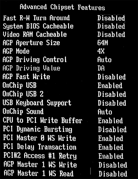
Advanced Chipset Features
This menu is linked to the chipset, which can be programmed in various ways. For example, there are various advanced settings for the AGP and PCI buses. If you use a USB-based keyboard you can specify that here. Then it will work in 16-bit DOS mode (real mode) as well.
The other settings
I have already mentioned that many users never end up fiddling with these Setup settings. There is therefore no reason for me to go through the other menus in detail. Let me just briefly discuss the main points:
Integrated Peripherals. This menu contains settings associated with the ATA and Super I/O controllers. For example, you can disable the floppy disk controller (FDC), so that a floppy disk drive cannot be connected. If the motherboard has a built-in sound device you might be able to disable it here.
Power management. This menu allows you to set how the various power saving functions should operate. There is nothing to benefit from this. The PC consumes the same energy with or without power management activated. On the hand power management can be quite irritating in daily use.
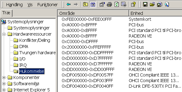
PnP and PCI Configurations. This menu allows you to allocated IRQs for each PCI slot yourself. You can also change the PCI bus timing, should you happen to want to. See Fig. 174.
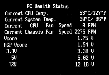
PC Health Status. This gives you a report on the CPUs current temperature and voltage, and how fast the cooling fans are whirring (if they are connected in the right way). This menu is used, for example, by overclockers, who are very keen to know that the PC is not burning out.
Frequency/Voltage Control. This menu allows you to set the clock multiplier factor for the CPU, if it allows this, and adjust the voltage for the processor core, AGP system and I/O bus. See also Fig. 123.
Set Supervisor and User password. These menus allow you to choose a supervisor password, which is used to protect the Setup settings. This is used in some schools, where certain students have a tendency to fiddle with the computers setup options.
Conclusion
The CMOS storage contains a number of essential items of system data, which are used by the startup programs. The user has the option to change these settings via the Setup program.
Many of the more advanced options are not relevant to normal users like us. They are linked to the controller chips on the motherboard, which can be configured in various ways, but there is no reason to change these settings. The motherboard manufacturer has already configured everything optimally, and they recommend in the manuals that you dont change anything. But if you are interested in your PC at the hardware level, you should definitely acquaint yourself with the facilities of the Setup program.
Resetting the CMOS storage
If you look at the main menu in Fig. 236, there are options there to reload the standard settings (Load Fail-Safe Defaults and Load Optimized Defaults). You can make use of this if, after playing around, you find that your settings no longer work.
It is a very good idea to write down what you change on a piece of paper especially the first time you work with Setup. Record the menu and setting you change, and what the value was before you changed it.
If it gets right out of hand, you can always reset the CMOS. You might need to do this, for example, if you set up password protection for Setup, and then forget the password.
The motherboard as a jumper which erases the CMOS data. You move the jumper, start the PC, and the data is erased. You then enter new data and move the jumper back again.
Another method is to remove the motherboard battery. This maintains the CMOS data, so all the data is erased if you briefly remove the battery (which you can ease out of its round plastic holder).
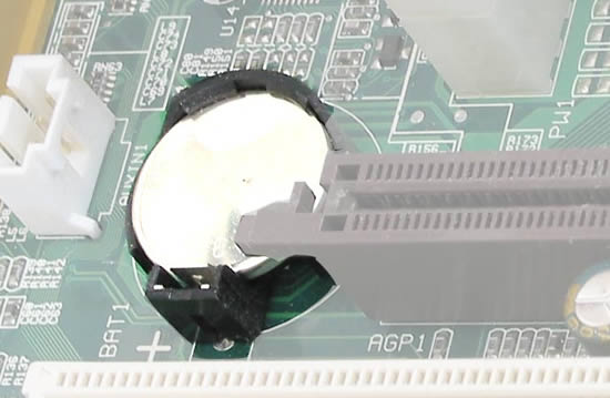
Modern batteries last for many years, but you may find that the battery has to be replaced one day. Youre sure to notice when this happens. The Setup program will ask you to enter the date, etc. every time you start the PC!
28. The BIOS programs
I have now described how the BIOS programs are stored in the motherboards ROM circuits, and how they look after starting up the PC and allow you to program various hardware devices via the Setup program. But thats not the whole truth about the BIOS. The BIOS is not only used during startup. And there is BIOS in other places, in addition to the motherboard. Let me conclude this examination of the PC architecture by describing the BIOS.
Using the BIOS
In the computers infancy, there were no operating systems. Applications (user programs) were written so that they controlled the PCs hardware directly. Every program, for example, had to be coded to fetch characters from the keyboard and to send characters to the screen. In order to make programming easier, all the program routines that created interfaces to hardware devices were gathered into a library. This collection became the Basic Input Output System the BIOS.
Today the BIOS is still a collection of program fragments which establish connections to certain hardware devices. The BIOS is still available to programmers, but the Windows operating system prefers to use its own drivers to communicate with hardware. Thus Windows has two ways of accessing each hardware device:
BIOS really has the same function as the drivers; its just an older
system. Whereas the BIOS routines are placed in the actual hardware, the drivers
are placed within the operating system. There is a BIOS routine, for example,
which enables the PC to read input from the keyboard. The BIOS is located, as
we have seen, in the ROM circuits on the motherboard. But it is also stored on
expansion cards in so-called adapter
The BIOS we find on the motherboard handles all the motherboards own devices. External adapters (e.g. video cards) also need BIOS, and this code is, of course, placed in ROM circuits in the device. During startup, all the BIOS is merged and allocated RAM addresses, so that these program fragments are available to the operating system.
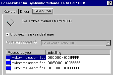 Figure 243. The Plug and Play system has its
own BIOS, which is loaded into a RAM address.
Figure 243. The Plug and Play system has its
own BIOS, which is loaded into a RAM address.
Thus both the drivers and the BIOS tailor the hardware devices for the operating system, so that everything works together:
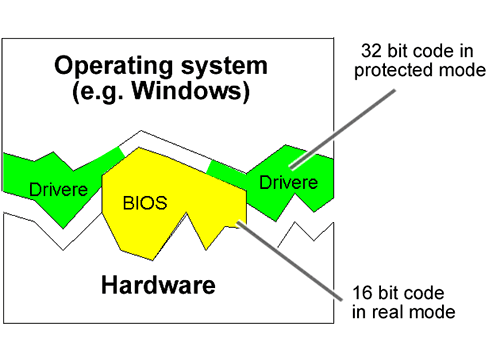
16 bit BIOS code
The BIOS routines are part of the very original PC architecture. They were therefore written in 16-bit code which suited the original 8088/86 processors, and which was executed in the slow real mode. The BIOS is the PCs oldest and most primitive program layer.
Since modern CPUs, and Windows, are a 32-bit environment, it is not appropriate to use the BIOS routines for anything beyond what is absolutely essential. During normal daily operations, Windows therefore uses its own 32-bit drivers to exchange data with hardware devices. These drivers work much faster, and can be constantly adapted to new hardware.
However, during startup, the BIOS is still important. At that time, the operating system hasnt yet been loaded, so the startup programs draw on the BIOS. And if you work with a 16-bit operating system (such as DOS), it will be using the BIOS to a large extent.
Advantages of 32-bit drivers
Windows drivers can write directly to all kinds of hardware bypassing the BIOS routines.
One example is the COM ports. If you use the BIOS routines attached to these, you cannot transmit any more than 9600 bits per second (baud) via a modem. But using Windows own drivers, much greater amounts of data can be transferred over the COM ports.
Thus in this situation the original BIOS routines are basically unusable. One could easily imagine that the BIOS could be upgraded to be more efficient. But that would presumably break the compatibility. So instead we continue to live with obsolete BIOS, but luckily it has little practical significance.
BIOS upgrades
The BIOS programs can be upgraded. Modern motherboards (as mentioned before) have their BIOS stored in flash ROM, which can be upgraded. You can obtain new BIOS software from your supplier or on the Internet.
To perform an upgrade you first download the new BIOS from the motherboard manufacturers web site and save it on a diskette. You then run this on the PC in DOS mode.
However, you shouldnt start to experiment with BIOS upgrades unless you are sure that you have understood the instructions 100%, and that you have obtained the correct version of the BIOS. Otherwise it can cause big problems.
Instead of BIOS
Intel plans to replace the (very) old BIOS system with a new set of programs. The new system is called EFI (Extensible Firmware Interface) and is in it self a complete little operating system. It has a graphical user interface. Where the old BIOS is written in the Assempler language, the new EFI is written in C, making it more easy accessable.
29. The end
We have now worked our way fairly thoroughly through the PCs architecture. I hope you have really learned something from the examination. The ongoing work is up to you. I recommend you take your time to analyse your own PC. You can learn a lot from that.
Getting help
There are a number of tools you can make use of when you start investigating:
It can also be very practical to have a startup disk with DOS on it. If you load this, you will get access to pure DOS, which you can learn a lot from working with.
Search on the Net
I have already mentioned that the Internet is a good source of knowledge on IT subjects. There are an incredible number of English language sites, which specialise in describing, analysing and commenting on various hardware items such as motherboards, processors, etc.
I wont promote any sites in particular. When I need information myself on a particular topic, I use the Google search engine, and I can find a handful of relevant sites in a matter of seconds. In my experience you can get a lot out of doing this.
If I was to mention a specific site, it would have to be www.geek.com. It is run by Rob Hughes, and every month he sends out a little newsletter, which I can warmly recommend. Rob talks about all the new processors, and developments in the area of RAM, chipsets, etc, and also provides links to other sites. It is very good, and free.
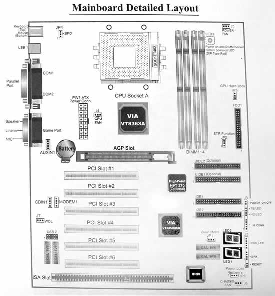 Figure 246. Your motherboard manual is worth
studying.
Figure 246. Your motherboard manual is worth
studying.
30. Glossary
Fairly early on in the guide I started to explain a number of terms. I will now conclude with even more of the same. Most of these expressions have been used in the guide; here is a brief explanation of them.AMR. Audio Modem Riser. A standard for small expansion cards which are mounted on the motherboard and which provide connectors for the motherboards built-in sound and modem functions. Only used in very cheap PC configurations.
BIOS. Basic Input Output System. Program code which provides simple control over a hardware device.
Bus Master. A controller property, which allows a PCI device to take control over the PCI bus, so that data can be exchanged directly with RAM. CMOS. Complementary Metal-Oxide Semiconductor. Really a name for the process technology used, among other things, for CPUs. There is a CMOS storage chip on the motherboard which contains a database of information about the motherboard and the other hardware devices. CSA. Communication Streaming Architecture. An Intel design, where the Gigabit LAN controller plugs directly into the north bridge.
DMA. Direct Memory Access. A system which allows an ISA device to move data directly to and from RAM.
DOS. Disk Operating System. A 16-bit operating system from the time before Windows. Can still be installed on any PC.
DRAM. Dynamic RAM. Storage cells which are used for standard RAM modules. Requires a constant refresh signal to remember the data.
ECC. Error Correcting Code. A type of RAM which can correct internal errors which might occur during program execution. Is used for DRAM in servers and in the CPUs internal cache.
ECP. Enhanced
EIDE. Enhanced IDE interface for hard disks. Also called PATA for Parallel ATA.
EPP. Enhanced
ESCD. Extended System Configuration Data. A list of the installed PCI devices. Included in the CMOS storage.
File system. A system for organising data at the sector level on, for example, a hard disk. E.g. FAT32, NTFS.
IDE. Integrated Drive Electronics. Hard disk interface.
IrDA. Infrared Data Association. Standard for wireless data transfer over short distances using infrared light (like your TV remote control).
Local bus. A bus (e.g. the system bus) which runs synchronously with the clock frequency in a connected device.
LPC. Low Pin Count. An Intel standard which is used, among other things, for non ISA-based Super I/O chips, designed with relatively few pins.
Mode. A state which an interface or a system can work in.
Multitasking. When a system can work on several jobs at the same time.
PCI. Peripheral Component Interconnect. The traditional motherboards standard I/O bus.
PCI Express. New standard replacing PCI and AGP.
PIO. Programmed I/O. Protocol for IDE/EIDE interfaces.
POST. Power On Self Test. The part of the BIOS programs which tests the PC during startup.
Protected mode. The 32-bit program state which replaced real mode.
Real mode. A 16-bit state which programs were limited to working in in the first CPUs.
Registers.
Tiny,
lightning fast RAM stores, built deep into the CPU.
RAID. Redundant Arrays of Inexpensive Disks.
SATA. Serial ATA.
SCSI. Small Computer System Interface. An intelligent
expansion bus. SRAM. Static RAM. A type of RAM which
(in contrast to DRAM) can maintain its data without a refresh signal. SRAM is
faster and more expensive than DRAM. SRAM is used, for example, for processor
caches. Yours sincerely, Michael Karbo. www.karbosguide.com