Copyright Michael Karbo and ELI Aps., Denmark, Europe.
Chapter 44. Hard disks, ATA and SATA
I am now finally going to describe the ATA interface, which has been mentioned several times earlier in the guide. The ATA interface is used for hard disks (as in Fig. 20, and the motherboards ATA controller is built into the chipsets south bridge, as shown in Fig. 195.
We have also seen, that ATA devices use bus mastering to exchange data directly with RAM. But what does this interface actually consist of? And why do new standards for hard disks keep coming out? We are going to look at that now.
History of the hard disk
It is critical that we have a place to save our programs and data when the PC is switched off. Otherwise it is useless. Twenty years ago, diskettes were used, but their capacity is very limited.
Right back
in 1957, IBM introduced the first fixed disk storage. It was a big thing with
50 disks that were 24
inches in diameter. This very early hard disk had a
capacity of 5 MB a huge storage space at the time, which cost $35,000 a year
to lease. One of IBMs models was called the 3030, and in the weapons-conscious
The first computer with a hard disk was IBMs RAMAC, which was used during the 1960 Olympics to calculate sports results. A bit later, in 1962, removable disk packs were developed a forerunner of the floppy disk. In 1964, the CRC algorithm was introduced. It provided greater security by checking and comparing data before and after it was written to the disk. In 1971, the first 8-inch diskettes came onto the market.
But it wasnt until the middle of the 1980s that people began to use hard disks in more standard PCs, and since then development has surged ahead. The capacity of a standard hard disk has actually become a thousand times greater in the period 1990-2000.
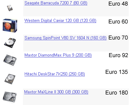
The standard users need for disk space (e.g. for digital photos, video and music) has grown in step with this, so that 120-250 GB of disk space or more is normal in many PCs a figure which will double over the next few years.
Hard disks are constantly being developed which have greater capacity and speed (the two go together, as we shall see), and there is therefore a constant need for new types of hard disk controllers. The companies leading the development are Maxtor, Western Digital, IBM/Hitachi and Seagate.
The physical disk
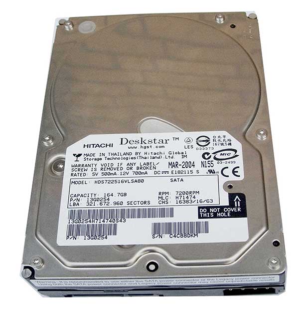
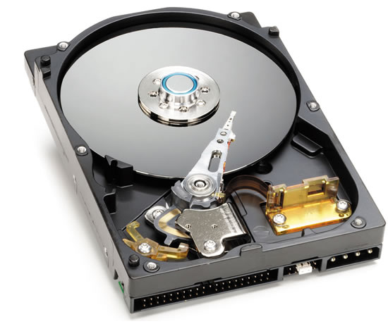
Hard disks consist of one or more magnetic plates mounted in a metal box. The standard size (as in Fig. 213) is about 10 x 14.5 x 2.5 cm, and such a device can contain hundreds of gigabytes of data. Inside the box, a number of glass or metal plates whir around at, for example, 5400 or 7200 revolutions per minute these being the two most common speeds.
The read/write heads hover over the magnetic plates, and can transfer data at a tremendous speed:
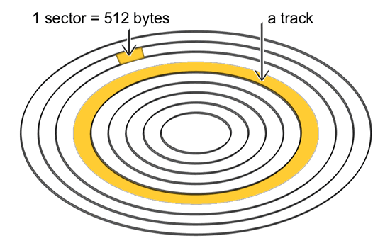
The actual read/write head is a tiny electromagnet. The magnet ends in a C-shaped head, the shape of which ensures that it virtually hovers above the magnetic plate. Under the read/write head are the disk tracks. These are thin rings packed with magnetic particles. These magnetic particles can be arranged in patterns of bits, which are translated into 0s and 1s by the electronics of the hard disk:
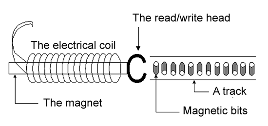
When the disk moves under the read/write head, it can either read the existing data or write new data to the disk:
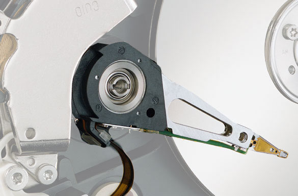
The read/write heads are the most expensive part of the hard disk. When the disk is switched off, the heads are parked in a special area, so that they will not be damaged during transport. In Fig. 216, the cover has been removed from a hard disk, and you can see the uppermost arm with its read/write head.
Tracks and sectors
The individual files are written across a number of disk sectors (at least one), and this task is handled by the file system.
The file system is part of the operating system, which the disk has to formatted with. In Windows 98, the FAT32 file system is used. In Windows 2000/XP, you can also use NTFS. They are different systems for organising files and folder structures on the hard disk. You can read more about the file system in my guide, Do it yourself DOS.
Hard disk development
New hard disk models are constantly being developed, and for each new generation, the capacity becomes greater. This is possible due to new read/write heads and magnetic plates which are more dense. When the magnetic density is increased, hard disks can be produced which have greater capacity for the same number of plates.
Another consequence of higher density is that the disks become faster, since they can transfer more data per rotation. There are simply more bits hidden in each track.
All hard disks have a certain amount of cache installed as 2 or 8 MB of fast RAM, which functions as a buffer. The cache helps ensure that the data gathered by the mechanics of the disk is optimally exploited.
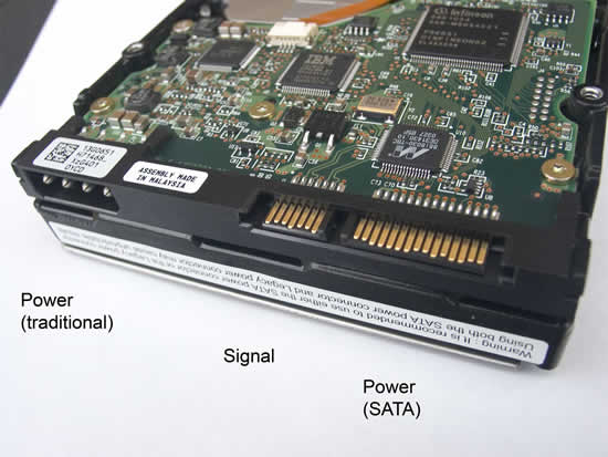
The new and faster hard disks are always followed by new types of interface, since the controller principles have to be upgraded as well in order to handle the large amounts of data. At the time of writing, the fastest ATA interface is called ATA/133, but it is about to be replaced with Serial ATA (see Fig. 221).
The hard disks interface
The hard disk is managed by a controller built into the actual unit. This controller works together with a similar controller linked to the PCs I/O bus (on the motherboard). I showed this setup in Fig. 20, in order to explain the concept of interface.
The interfaces job is to move data between the hard disk sectors and the I/O bus as fast as possible. It consists of:
In the old days, interfaces such as ST-506 and ESDI were used. The ATA (AT Attachment) interfaces are based on the IDE standard (Integrated Drive Electronics). The names, IDE and ATA are owned by Western Digital, but are used anyway in everyday language.
Enhanced IDE
The IDE standard wasnt especially fast, and couldnt handle hard disks bigger than 528 MB. So the ATA standard came out in the mid-1990s, and is still used today for cheap, high-performance, mass-produced hard disks. ATA is an enhanced edition of IDE, where the interface was moved from the ISA bus to the high-speed PCI bus. In principle, ATA (or parallel ATA) can be used for a number of different devices. The most common are:
ATA was developed as a cheap, all-round interface, designed for the different types of drives.
Host controller with two channels
The ATA interface can be seen as a bus, which is managed by a host controller. Up to four devices can be connected per host controller, and the devices connect directly to the motherboard.
The slightly unusual thing about the ATA interface is that there are two channels, which can each have two devices connected. They are called the primary and secondary channels. If two devices are connected to one channel, they have to be configured as one master and one slave device:
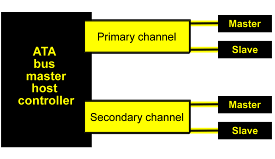
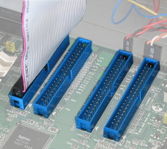
These four channels are standard on todays motherboards using parallel ATA. Motherboards typically have connectors for two ATA cables, which can each connect two devices (master and slave).
These rectangular, male ATA connectors are placed in a fairly accessible location, and are used to connect the ribbon cables which fit hard disks and CD/DVD drives.
Transfer speeds and protocols
There are many ATA versions. The protocol has been changed over the years, but on the whole, the products are backward compatible.
This means that you can readily connect an old CD-ROM drive which uses the PIO 3 protocol, for example, to a modern motherboard with an ATA/133 controller. The drive just wont be any quicker as a result. The shift from parallel ATA/133 to Serial ATA is more profound. Here we use a different type of controller and new cables.
The various protocols have different transfer speeds, as shown in the table below.
|
Max. theoretical transfer rate |
|
|
PIO 3 |
13.3 MB/second |
|
PIO 4 |
16.6 MB/second |
|
Ultra DMA (ATA/33) |
33 MB/second |
|
ATA/66 |
66 MB/second |
|
ATA/100 |
100 MB/second |
|
ATA/133 |
133 MB/second |
|
SATA |
150 MB/second |
Figure 221. The various versions of the ATA standard.
The transfer speeds listed apply to the interface. Few hard disks can deliver more than 80 MB/second, but even so, its still good to have the fastest possible interface. If two hard disks are used on the same controller, or if disks with a large cache are used, there can be a need for big bandwidth for short periods.
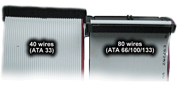
With the ATA/66 standard, a new type of ATA cable was introduced. Hard disk cables normally have 40 conductors, but in the new version this is extended to 80, as each wire is balanced by a ground connection. This reduces electrical noise and allows for greater bandwidth.
Parallel ATA setup
If you build your own PC or upgrade it using a new hard disk or CD/DVD drive, it is important that you know the limitations of the parallel ATA system.
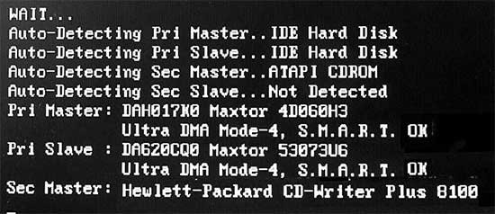
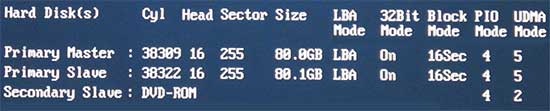
Modern motherboards can automatically recognize ATA devices. This means that, in principle, you can install your drive and start the PC, and it should work. You can follow the startup program while it installs the drive, as shown in Fig. 223, where two hard disks and CD burner are installed.
In the first four lines, the controller auto detects the four channels for connected devices. It then mounts (configures) the two Maxtor hard disks on the primary channel, and finally the HP burner on the secondary channel. You can read this in the lines below:
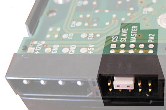
Each ATA device has a small area containing jumpers which are used to set whether it is the master or slave device. If the startup is to proceed as painlessly as in Fig. 225, the jumpers have to set correctly on all devices, and of course the cables have to correctly connected.
Multitasking and protocol limitations
But this is not the case if two disks are connected to the same ATA channel. They cannot multitask. Either the master is working, or the slave is working, but not both at the same time. It is therefore best to install two hard disks on separate channels if they have to work at the same time.
The two main channels (primary and secondary ATA) can each run their own protocol, but the master/slave channels cannot do this. If you install two devices which use different protocols on the same channel, you run the risk that the slowest device will determine the speed for the whole channel. The optimal solution, therefore, is to connect your hard disk as the master on, for example, the primary channel, without connecting a CD drive as a slave device.
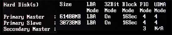
Look at the following picture. The CD burner is sitting by itself on the secondary ATA channel (Secondary Master), and this is for the sake of the hard disks. The two hard disks have been placed on the primary channel, since they both use the same protocol (ATA/66 in this case). The devices protocols can be seen on the right in the last two columns (PIO and UDMA mode):
If you use all four ATA connections, it might look like this:
|
ATA connection |
Device |
|
Primary, master |
Hard disk 1 |
|
Primary, slave |
Hard disk 2 |
|
Secondary, master |
CD ROM burner |
|
Secondary, slave |
DVD drive |
Figure 226. All four ATA channels are being used.
A problem arises when you need to connect two hard disks, in addition to a CD/DVD drive or drives. This is not possible, without compromising on quality. The two hard disks have to placed on the same channel, since CD drives generally operate using a slower protocol. But this does not allow for the optimal utilisation of the hard disks they should ideally have their own channel, all to themselves, for the sake of multitasking.
This is why motherboards with an extra built-in ATA RAID controller are much more preferable with these you can install up to 8 ATA devices in the same PC (see Fig. 220. But if you ensure, right from the start, that you put a big hard disk in the PC, this helps.
ATA RAID
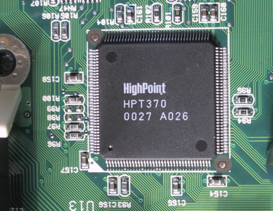
The ATA interface can quickly become a bottleneck, as I have just described. I therefore warmly recommend using a motherboard with an extra built-in RAID controller. This doubles the number of possible devices. Many motherboards (like my own from Epox) have both a standard ATA device in the south bridge, and an extra controller (from HighPoint or Promise), and this provides much greater flexibility.
Another option is to buy and external RAID controller which can be mounted in an expansion slot. This will also allow for a further four ATA devices to be connected. For years I used the Fasttrack controller from Promise, which you can see in Fig. 170. If you look carefully you can see two ATA connectors at the top of the card.
Since the ATA limitations have become more pronounced in recent years, most motherboards today can be bought with an extra built-in RAID controller, and thats the easiest solution.
The RAID controller actually allows for striping of drives (see Fig. 206, but you may also simply use it as an extra ATA controller.
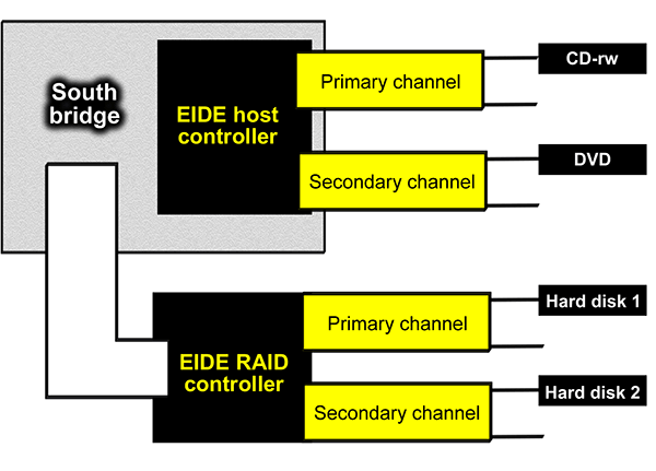
This way one can use two hard disks, which each have an ATA channel all to themselves. Just as the two optical drives each have their own channel also. Perfect! The hard disks run at full speed, and the CD drives have the optimal configuration.
SATA - Serial ATA
The old well-known, parallel ATA system is clumsy and in-flexible. The big ribbon cables take up to much room in the computer cabinet and they reduce the circulation of air. The cables have a fixed length and they make it difficult to mount the harddisks.
Furthermore the PATA-system with master/slave channels is difficult to work with, and the band width is limited.
|
The successor to the ATA system is called Serial ATA. Here we have an interface using small handy cables with only 7 wires in stead of the big 40/80-wired cables used in the Parallel ATA-interface. |
|
Serial ATA is a high-speed serial interface in family with Ethernet, USB, FireWire and AMD's Hyper Transport. All these interfaces use a serial technology. They only have two channels: one receiving data and one transmitting them. This can be achieved with a very simple cabling. The data communication only requires 0,25 Volt compared to the 5 Volt of parallel ATA.
The existing PATA system has a limit of 128 GB volume harddisks. This gave problems with the first 160 GB disks. The parallel system only operates with 28 bit data for addressing the disks. It can only adress 228 sectors. Since each sector on the hard disk holds 512 bytes of data, we have 228 times 512 bytes data, which is 128 GB.
To use bigger hard disks, the operating system has to address the sectors directly. In Windows XP this function is called 48 bit LBA, and is it has caused some troubles to have it work. Using Serial ATA, there are no problems with bigger hard disks.
More about Serial ATA:
The controlling logic of Serial ATA is much more sophisticated (and SCSI-like) than in the traditional ATA interface. Serial ATA can process several commands at the same time and re-arrange them for better efficiency.
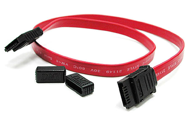
Figure 231. Cable for Serial ATA.
Some motherboards available in 2004 have SATA controllers based on a bridge. In reality it is just a converter, giving an old-fashioned PATA controller SATA functionality.
These boards take both parallel and serial ATA-disks. This sis great when you have old hard disks, you need to reuse with a new motherboard.
However, this bridged controller gives no room for better bandwidth. So to se better performance from the SATA hard disks, we need a new generation of motherboards without PATA-compatibility.
