
Parameterized word length
Asynchronous clear
Synchronous register parallel load
Behavioral simulation model in VHDL and Verilog
ACT 1, ACT 2, ACT 3, 3200DX, MX, SX, SX-A, eX, 500K, PA, Axcelerator, ProASIC3/E, Fusion
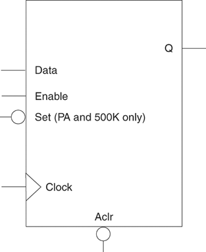
Storage registers have a parallel-in/parallel-out (PIPO) architecture. The registers are WIDTH bits. They are clocked on the rising (RISE) or falling (FALL) edge of the clock Clock (CLK_EDGE).
The Clear signal (CLR_POLARITY), active high or low, provides an asynchronous reset of the registers to “000…0”. You may choose to not implement the reset function.
The Enable signal (EN_POLARITY), active high or low, provides a synchronous load enable operation with respect to the Clock signal. You can choose to not implement this function. Storage registers are then loaded with a new value every clock cycle.
The Set signal, active high or low, provides an asynchronous set of the registers to "1111...1". You may choose not to implement the Set function.
|
Port Description |
|
Port Name |
Size |
Type |
Req./Opt. |
Function |
|
Data |
WIDTH |
input |
Req. |
Register load input |
|
Aclr |
1 |
input |
Opt. |
Asynchronous register reset |
|
Enable |
1 |
input |
Opt. |
Synchronous Parallel load enable |
|
Clock |
1 |
input |
Req. |
Clock |
|
Q |
WIDTH |
output |
Req. |
Register output bus |
|
Parameter Description |
|
Parameter |
Family |
Value |
Function |
|
WIDTH |
500K, PA |
1-512 |
Word length of Data and Q |
|
All others |
1-99 |
||
|
CLR_POLARITY |
All |
0 1 2 |
Aclr can be active low, active high, or not used |
|
EN_POLARITY |
All |
0 1 2 |
Enable can be active low or active high |
|
CLK_EDGE |
All |
RISE FALL |
Clock can be rising or falling |
|
Parameter |
Value |
|
CLR_FANIN |
AUTO MANUAL |
|
CLR_VAL |
<val> [default value for AUTO is 8, 1 for MANUAL] |
|
EN_FANIN |
AUTO MANUAL |
|
EN_VAL |
<val> [default value for AUTO is 6, 1 for MANUAL] |
|
CLK_FANIN |
AUTO MANUAL |
|
CLK_VAL |
<val> [default value for AUTO is 8, 1 for MANUAL] |
|
Implementation Parameters |
|
Parameter |
Value |
Description |
|
LPMTYPE |
LPM_DFF |
Register category |
|
LPM_HINT |
PIPO |
Parallel-in/Parallel-out |
|
Functional Description A |
|
Data |
Aclr |
Enable |
Clock |
Q |
|
X |
0 |
X |
X |
0’s |
|
X |
1 |
X |
Ø |
Qn |
|
X |
1 |
0 |
¦ |
Qn |
|
m |
1 |
1 |
¦ |
Qn+1 = m |
|
A. Assume Aclr is active low, Enable is active high, Clock is rising (edge-triggered). |