Sealevel’s GPS Modifications
Sealevel Systems offers two GPS options designed specifically for the Rockwell Collins GPS
receiver. This receiver outputs its data at 76.8Kbps. This is a nonstandard data rate and
is not achievable through standard COM: ports thus requiring a modification. The main part
of the modification requires changing the clock frequency in order to match the 76.8Kbps
data rate. The GPS modified boards are also able to communicate at several standard data
rates as well and a brief explanation of choosing a data rate will help in understanding
how to achieve data rates different than 76.8Kbps with the GPS boards. All standard COM:
ports are based on a clock frequency of 1.8432Mhz. The highest speed available using this
clock frequency is 115.2Kbps. This is a data rate most all have seen and/or used. The way
that 115.2 is derived from the 1.8432Mhz clock frequency is as follows:Clock
Frequency/16=max rate. Example: 1843200/16=115200. If you are writing a divisor to the
UART a divisor of 1 will give you this 115.2Kbps. In the case of the GPS modification we
have altered the clock frequency to 1.2288Mhz. Therefore the maximum data rate would be
1228800/16=76800. Again, a divisor of 1 in this case would give you a data rate of
76.8Kbps. If you are running in Windows and have a GPS modified card and have to pick the
standard Window’s data rates you would choose 115.2Kbps. This would give you actually
76.8Kbps because the clock is slower than the standard clock by 0.66666…. That gives
us the equation of 115200X0.6666=76800. In a number of cases people will use this card to
receive the Rockwell Collins GPS rate of 76.8Kbps but need to transmit at 19.2Kbps. The
question here would be how do you get 19.2Kbps. 19200/0.6666=28800. That would be that
data rate that one would choose. Remember that the ACTUAL data rate is the data rate
chosen multiplied by 0.6666. Sealevel Systems offers two different GPS modifications.
These differ enough that a description is necessary. The first modification is the GPS.
The part number you would order and the part number that is present on the board would be
#-GPS. An example would be 3087-GPS. The above explanation suffices enough to describe the
modification. By following all of the above you should have no trouble using the GPS
modification. The second GPS modification is the GPS1P. Again, an example of the part
number would be 3087-GPS1P. This modification was done out of the need for a particular US
DOD specification. Rockwell Collins performed the project and in its original state had
nothing to do with GPS reception, but rather a gun camera mounted on an F4. The card is
modified so that the receive side is “hardwired” to receive at 76.8Kbps and the
transmit side is programmable just like any other serial port. However, the same offset of
0.6666 applies because the clock frequency is changed just as in the GPS modification.
This was done so that one could receive at 76.8Kbps but transmit at, say, 19.2Kbps on the
same port. No matter what you do in terms of setting the data rate the receive side is
always gong to be 76.8Kbps. If you have a GPS1P modification and wish to use our test
software to verify that the card is working you must set the data rate to 115.2Kbps. This
results in the transmit side sending at 76.8Kbps, (115200x0.6666=76800), and the receive
side will always be 76.8Kbps. If you have any other questions about the Sealevel Systems
GPS modifications please contact Sealevel Systems Technical Support at or call
864.843.4343. <back to top>
 Do you have sample windows programs for writing
to a serial port?
Do you have sample windows programs for writing
to a serial port?
We have three sample programs: a terminal program, toggling modem
control signals, and finding the UART type on a card available. These are simple windows
console apps without the GUI. To get a better understanding you should find the
Microsoft’s Software Developers Toolkit, (SDK), invaluable. The SDK contains a number
of examples for windows users. Click
here to download our sample programs.<back to top>
Are there any tools available for help in writing
serial programs.
Yes. PortMon can be a big help. You can find this program at Sysinternals website. You will find other helpful
programs there as well along with source code, free to download. PortMon has helped us
solve problems in a fraction of the time it would normally take.<back to
top>
When I use your window’s serial driver is
there anything special I need to know?
No. Our driver looks exactly like the windows driver using the same
API. Our driver does offer extended features like RS-485 RTS control, support for advanced
UARTS. Also, it supports sharing interrupts in 95/98. <back to top>
Do your products support sharing interrupts with
other devices?
Yes and no. In 95/98 the interrupt sharing is for our ISA products
only. For PCI based products, interrupt sharing works only if the other device(s) also
has/have the same feature. The interrupt sharing is a bit tricky because one never really
knows what other devices are doing, especially onboard devices. Onboard devices do not
like to share. It is always best to seek a unique IRQ for our devices. <back
to top>
If I have to reinstall one of your boards for
whatever reason what is the best way.
First remove the card in software then power down. Do a cold
start. This will help make sure the registry entries are cleared before reinstalling.
There is no reason to uninstall the software itself.<back to top>
Will a standard DB25 to DB9 adaptor work with my
RS-422/485 board?
No, this will not work because the adaptor is made for RS-232
and the pin-out is different. You will need to construct your own adaptor.<back
to top>
Will standard off the shelf cables work with my
RS-422/485 Board?
No. These cables are made with RS-232 in mind and do not conform
to the pin-out for RS422-485. It is best to construct your own cables from shielded,
twisted pair. Do NOT connect the shield on both ends of the cable, only on one end. <back to top>
General
Technical Support Questions:
How do I determine what board I have?
There is a four digit number that begins with 3, 4, or 7 followed by a
Revision letter located on the board as part of the copper or silkscreen. <back
to top>
I’ve lost my Manual. How can I get another?
Manuals are provided in a Word for Windows format from our Web site.
Simply click on the following link ftp1.sealevel.com
and select your part number. Alternatively, we would be glad to fax a copy or mail a copy
at your request. <back to top>
Where can I obtain a user’s manual for the
85230 chip used on the synchronous boards?
What synchronous driver support do you have for
the synchronous PCMCIA card?
When should I consider upgrading UARTS?
Several factors must be considered when upgrading to a 16650, 16750,
16850, etc. The upgraded UARTS offer deeper FIFO levels, which help in buffering data.
Typically when running high data rates, i.e., above 115.2Kbs a 16650 or higher would help
insure no data loss. Also, when sharing one interrupt with several ports that may be
opened at the same time an upgraded UART helps insure data integrity. Another factor to
consider is high throughput rate even though the data rate may be relatively low.
Upgrading under that circumstance is a necessity if sharing an interrupt or if heavy disk
activity may be encountered while using COM: ports.
For detailed information on UART performance, including optimal FIFO settings, please click Here
<back to top>
I noticed that you have a replacement serial
driver for Windows 95/98/NT. What does it do and do I have to use it?
The serial replacement driver offers several enhancements over the
standard Windows driver. It has support for advanced UARTS such as the 16750 and 16850.
Without the driver you would not have access to the larger FIFO’s on these UARTS.
There is also 2-wire RS 485 support, which can be used with Sealevel adapters that do not
have the Auto Enable circuit, (Ultra Series). The driver allows the user to select RTS
control or Real Time RS 485 and has echo suppression options. The driver also allows one
to share interrupts in Windows 95/98 on adapters with an interrupt status port. The
standard Windows 95/98 serial driver does not support an interrupt status port, however,
the Windows NT standard serial driver does support an interrupt status port. If you are
using a PCI adapter in NT, want to share interrupts with a multiport adapter in 95/98, or
have an advanced UART you must use the driver. You do not have to use the driver with a
mulitport adapter in NT or if you do not plan to share interrupts in 95/98. However, there
is an installation utility for NT that makes installation of multiport adapters much
easier and if you are installing a multiport adapter in 95/98, using the INF file included
makes installation much easier as well. If you have any questions about our SeaCom serial
driver please contact technical support at 864.843.4343 or email support@sealevel.com.<back to
top>
Can I share an interrupt on a multi-port board in
Windows 95/98?
You can, provided you use a board that contains an interrupt status
port and our Windows 95/98 serial driver. Check our Products section to see which cards
contain an interrupt status port. Also, the PCI multi-port boards use one interrupt. One
interrupt can also be shared with multiple Sealevel Systems adapters. <back
to top>
Can my ISA card share an interrupt with another
device?
The ISA devices are interrupt exclusive meaning that they need their
own interrupt. However, like devices from Sealevel Systems can share an interrupt provided
they have an interrupt status port. <back to top>
When installing the Windows software that
supports a PCI adapter, should the adapter be installed before the software?
Always install the software before installing a PCI card. After
installing the software, power the computer off and install the PCI card in an available
slot and power up. <back to top>
Is there anyway I can automate the software
installation in Windows NT when installing a PCI adapter?
If you have Sealevel Systems PCI adapters to install in a number of
machines, it is possible to do an "unattended" installation by using a simple
batch file. This will work only when installing a PCI adapter in Windows NT. Remember,
too, that the software must be installed before the adapter. To create this batch file you
must first do a normal installation on one machine so that all files are extracted. Then
copy the following files, which will be used in the batch file. The main file that you
have to copy to other machines is:
serial.sys -> \ winnt or winnt35 \ system32 \ drivers
If you want to install our Advanced Ports Control Panel application, which shows all ports
installed and their associated resources along with if the ports are
valid or not, copy this file:
serial.cpl -> \ winnt or winnt35 \ system32
If you want the help files and the utility program WinSSD copy these files:
serial.hlp -> \ winnt or winnt35 \ system32
winssd.exe -> \ program files \ serial utilities
winssd.hlp -> \ program files \ serial utilities
All of the above files will be found only after a normal installation. Our installation
takes the original serial.sys and renames it to ntcom.sys for backup reasons. The
serial.cpl will automatically show in Control Panel. You will need to provide a shortcut
for WinSSD if you choose to install it. Again, the only file that you have to use is our
serial.sys file. You may or may not want to use the other files.
Next create a batch file that first renames \ winnt or winnt35 \ system32 \
drivers\serial.sys to ntcom.sys
Next copy our serial.sys to \winnt or winnt35 \ system32 \ drivers\.
That is all that is necessary. After running the batch file power down the machine and
insert the adapter and power up. <back to top>
When should the Plug and Play, (PNP), BIOS
support be turned on?
Typically PNP should be turned on when running Windows 95/98 and
turned off when running Windows NT, DOS, etc. However, there are times when this does not
hold true such as when you wish to reserve IRQ’s for ISA devices. This is a function
of your BIOS and the options it offers. <back to top>
What resources can be modified when using a PCI
adapter?
In Windows 95/98 the I/O address can be modified which is described in
detail in the board’s manual. Windows NT does not allow the user to change any
resources. If any resources need to be changed the adapter can be moved to a different PCI
slot which will, in most cases, change the resources. When running DOS both the I/O
address and IRQ can be changed by using the utility SETPCI.exe found in the dos\pci\
directory on disk 1 of the serial utilities disk set, (SUD). Since BIOS allocates the
resources each time the computer is turned on the most efficient way to use SETPCI is by
loading it in you autoexec.bat file. <back to top>
How can I change IRQ’s assigned to my PCI
communication board?
Because the BIOS allocates resources for the PCI bus, IRQ’s can
only be changed by moving your adapter to a different PCI slot. However, if you have only
one free IRQ or no IRQ’s available the IRQ assigned to the PCI adapter may not
change. If you are running DOS refer to the above question on changing resources. <back to top>
What pins should I connect when doing a loop back
test with your test software, SSD.exe or WinSSD.exe? Do all pins need to be connected?
RS232: TX > RX, RTS > CTS > RI, DTR > DCD > DSR
RS422/485: TX+ > RX+, TX- > RX-, RTS+ > CTS+, RTS- >CTS-
RS530: TX+ > RX+, TX- > RX-, RTS+ >CTS+, RTS- > CTS-, DSR+ > DCD+ > DTR+
DSR- > DCD- > DTR-
Unless you need the modem control signals such as RTS, CTS, DCD, DTR, DSR, or RI there is
no need to connect these pins for a loop-back test. The TX and RX pins are necessary.
Please refer to your manual for the correct pin numbers for the above pins or download the
Constructing Cables/Loopbacks for Testing document for more details on pin numbers and
electrical interfaces. <back to top>
Why does an old version of WinSSD cause my system
to crash when using your USB devices?
Some older versions of WinSSD contain code that aggravates an issue
with our USB driver. This occurs when a USB COM port is opened, data is sent using the
BERT function, and WinSSD is closed using either the Exit button or the Close Window
button. Your system may blue-screen or otherwise hang. This is because data is being sent
to the port at the same time as the port is being closed. To work around, always close the
port from the Port Information tab before closing WinSSD. This problem has been fixed in
subsequent releases of WinSSD. Click here
to upgrade. <back to top>
Can I use the RS-232 cable I have been previously
using with my new RS-485 adapter?
The cable you previously used with your RS-232 adapter may use a
different pin-out than what is required for RS-422/485. RS-422/485 does not specify a
mechanical connection, only electrical signal characteristics. The cable that you
previously used may have a different pin connection. Verify the board’s pin-out with
your device and determine what connections are necessary. <back to
top>
I have a laptop with Windows NT installed and
cannot get your PCMCIA serial card to be recognized. What do I need to do?
NT PCMCIA services must be started manually the first time that the
PCMCIA socket is used. This is done by choosing Devices in Control Panel and finding
PCMCIA, then click on Start. <back to top>
What is the maximum distance I can run my cable
with your RS-232 cards and RS-422/485 cards?
The specification for RS-232 calls for a maximum distance of 50 feet
at 20Kbps and the RS-422/485 specification calls for a maximum of 5000 feet at 9600Bps.
Data rates are a function of the distance of the cable. The shorter the cable length the
higher the data rate that can achieved. <back to top>
What is the maximum data rate of Sealevel Systems
COM: cards?
For cards shipped with an oscillator value of 7.3728Mhz the maximum
rate is 460.8Kbps. For cards having the 1.8432Mhz oscillator the maximum rate is
115.2Kbps. Remember these are maximum values and not necessarily achievable values. There
are many factors that must be considered when trying to run maximum data rates. Cable
length, system overhead and performance, number of ports used at the same time, noise
conditions, etc. If you have further questions contact Technical Support at 864.843.4343. <back to top>
How many COM: ports will DOS support?
Typically DOS supports four COM: ports: COM: 1 – COM: 4,
addresses 03f8, 02f8, 03ef, 02ef respectively, with COM:’s 1 and 3 using IRQ 4 and
COM:’s 2 and 4 using IRQ 3. If your application software has the ability to write to
a specific address such as 0280 or 0300 hex you can use as many COM: ports as use like
provided you use an address that is not used by any other device. <back
to top>
Can I use more than four COM: ports in Windows
3.1?
You can, provided that you use a serial driver replacement such as
HiCom/9, our part number 6400. This driver supports up to nine COM: ports and interrupt
sharing if the COM: adapter has an interrupt status port. Refer to our products section
for boards that have an interrupt status port. <back to top>
I have an older Sealevel Systems board and was
wondering if you had a replacement?
We have newer boards that can replace most boards manufactured by
Sealevel Systems. We also have limited support for some older boards and may be able to
replace the older board you currently have if your application requires the same adapter. <back to top>
What is Windows NT Remote Access Service, (RAS),
and can a Sealevel System’s adapter be used with this?
Windows NT Remote Access Service, RAS for short, provides a means for
connecting computers together through a Windows NT Server. This connection could be as
simple as connecting serial ports together or using modems to dial into the NT server. A
Sealevel System’s eight port RS-232 card such as the 3420 for the ISA bus or the 7801
for the PCI bus, when installed in the Windows NT Server, would allow eight individual
connections. Multiple cards could also be used in the server to allow even more
connections. In small locations where a number of computers are close to each other, the
serial port on the workstations could be connected to the serial ports of the Server and
each workstation could use a dial up connection connected straight to the serial port to
"dial" into the server. This is a simple means of having a dial up network in a
small location without having to install network cards in every machine. To access the
server from remote locations, a modem would be attached to each "dial-in" serial
port on the server and every machine offsite would have a modem to "call" the
server. This would allow users to access the server while offsite. To use RAS you must
first install the service on both the Server and Workstations. This is found in Network
Neighborhood, Properties, Add, RAS. On the Server you would then add the connections which
would be attached to each serial port. These could be direct or through a modem. You would
then add the Dial Up connections on each Workstation to the serial ports. These
connections would either be direct, (when not using a modem), or through a modem.<back to top>
Synchronous Communications
Boards Questions:
Could you explain synchronous communications?
Synchronous Communications is used for applications that require
higher data rates and greater error checking procedures. Character synchronization and bit
duration are handled differently than asynchronous communications. Bit duration in
synchronous communications is not necessarily pre-defined at both the transmitting and
receiving ends. Typically, a clock signal is provided in addition to the data signal. This
clock signal will mark the beginning of a bit cell on a pre-defined transmission. The
source of the clock is predetermined and sometimes multiple clock signals are available.
For example, if two nodes want to establish synchronous communications, point A could
supply a clock to point B that would define all bit boundaries that A transmitted to B.
Point B could also supply a clock to point A that would correspond to the data that A
received from B. This example demonstrates how communications could take place between two
nodes at completely different data rates.
Character synchronization with synchronous communications is also very different from the
asynchronous method of using start and stop bits to define the beginning and end of a
character. When using synchronous communications, a pre-defined character or sequence of
characters is used to let the receiving end know when to start character assembly. This
pre-defined character is called a sync character or sync flag. Once the sync flag is
received, the communications device will start character assembly. Sync characters are
typically transmitted while the communications line is idle or immediately before a block
of information is transmitted. To illustrate with an example, let's assume that we are
communicating using eight bits per character. Point A is receiving a clock from point B
and sampling the receive data pin on every upward clock transition. Once point A receives
the pre-defined bit pattern (sync flag), the next eight bits are assembled into a valid
character. The following eight bits are also assembled into a character. This assembly
will repeat until another pre-defined sequence of bits is received (either another sync
flag or a bit combination that signals the end of the text, i.e., EOT). The actual sync
flag and protocol varies depending on the sync format (SDLC, BISYNC, etc.). <back
to top>
What is the maximum speed of my ACB Card?
Typically shipped, the maximum data rate is 1.8432Mbps. This number is
the result of a mathematical calculation based on the oscillator value on the card. Actual
maximum data rates may vary depending on cable length, type of driver, operating system
overhead, disk activity, etc. <back to top>
What driver support do you have for you ACB
Synchronous boards?
For DOS we have HDLC/SDLC and an Asynchronous driver. For Windows 3.1
an HDLC/SDLC driver. For Windows 95/98 an HDLC/SDLC driver. For Windows NT an HDLC/SLDC
and an Asynchronous driver. <back to top>
Where can I get the latest Windows drivers?
I have your Windows drivers but am wondering
where to start.
For a detailed description on using our windows drivers download the
document, "Getting Started with the ACB Synchronous Boards." <back
to top>
How do I connect my RS-449 CSU/DSU with your ACB
cards?
RS-449 is an older specification that has been replaced by the EIA/TIA
with RS-530. Sealevel Systems has a DB-37 to DB-25 adapter cable that will facilitate this
conversion. For more information contact technical support at 864.843.4343 or email support@sealevel.com. <back to
top>
My ACB adapter does not show up under Devices in
Windows 95/98. Is that a problem?
The driver and its system.ini settings reserve the resources for the
ACB card. The ACB card will not show up under devices. However, if you are writing your
own driver and need to install the card you can do so by installing it as an unsupported
device. <back to top>
I need to test my ACB card with a loop-back. What
clock pins do I need to connect?
After connecting the TX and RX pins it is necessary to connect the
TSET, (clock output) to RXC, (clock input). Do not use TXC as a clock output unless it is
configured as an output and your application needs TXC. In most cases TSET should be used
as the board’s output clock. If you are unsure, contact technical support for further
information. Also, refer to the Getting Started with the ACB Synchronous Boards for a
detailed explanation on testing your ACB adapter card. <back to top>
Do you have any utilities for calculating data
rates or oscillator values?
On the ACB Tool Kit disk in the \utilities directory are two programs,
ACBBAUD and ACBOSC which you should find very useful in determining oscillators values,
divisors, and data rates when using the ACB family of communication boards. <back
to top>
I need a non standard data rate with my ACB
board. Can you help?
Sealevel Systems is dedicated to providing customer satisfaction,
including the modification of existing product to customer requirements. If your non
standard data rate cannot be achieved with the standard oscillator we can replace it with
one that will generate your data rate. This also includes getting non standard oscillator
values. Call technical support at 864.843.4343 or email your requirements to modifications@sealevel.com. <back
to top>
I have to write my own application, do you have
any sample programs with source code to help?
For Microsoft Window’s users the programs MFCTERM and CONTEST are
two sample programs that contain the code that you would need to include with your
application to make calls to our driver. CONTEST is the simpler of the two. If you have
installed the SeaMAC software, these programs are located in the seamac\samples directory.
The source for the window’s dll will be found in the seamac\library directory. For
DOS users there are several types of sample programs in the \samples directory of the ACB
Developer’s Toolkit disk. Please refer to the text file associated with the sample
programs for a description of each one. <back to top>
Where are the definitions for your SeaMAC API
calls?
All API functions are defined in the SeaMAC help file under
Programmers Application Interface. There you will find the definitions along with examples
of how to use the function calls. The SeaMAC help file is installed in the SeaMAC
directory and can be accessed through the SeaMAC Start, Programs, SeaMAC folder.<back to top>
Should I use the DMA Terminal Count when using
your SeaMAC synchronous drivers?
No. The DMA Terminal Count is used only for the SeaMAC asynchronous
driver. Trying to use the DMA Terminal Count with the synchronous driver will cause
failures in transmission.<back to top>
Is there a Windows 95/98 asynchronous driver for
your ACB cards?
No. At present there is no asynchronous 95/98 driver, only an NT
asynchronous driver.<back to top>
How many cards and ports will your NT SeaMAC
driver support?
Do I have to use DMA when using Sealevel’s
synchronous drivers?
Yes, at least one DMA channel must be used. Use a single channel if
you are communicating using half-duplex or are only transmitting or receiving but not
both. If you want to transmit and receive at the same time you must use two DMA channels.<back to top>
Digital
I/O Boards Questions:
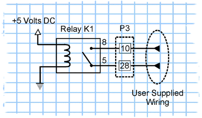
Where can I get a sample wiring diagram of a reed
relay output circuit?
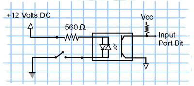
Where can I get a sample wiring diagram of an
input circuit?

