 |

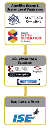
Design Flow
Xilinx now provides a complete front to back design flow
with Xilinx ISE v4.1i and XST (Xilinx Synthesis Tool).

|
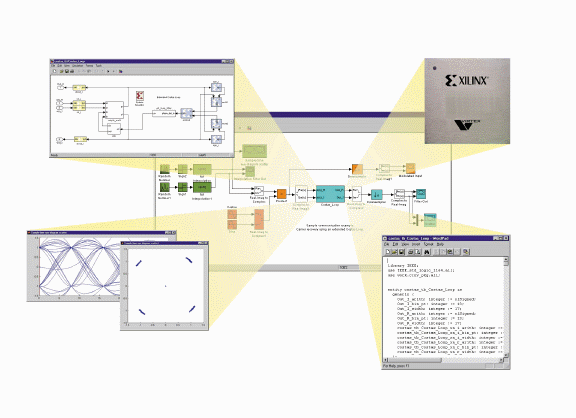
Use Simulink and the Xilinx Blockset to create and model your
DSP system.
Use System Generator to compile your Simulink model into a
hardware realization.
Use an HDL simulator and a synthesis compiler to simulate
and compile the HDL code, cores and test vectors that are
automatically produced by the System Generator.
Use the Xilinx ISE implementation tools (translate, place and route)
to produce a bitstream for download into an FPGA device
|
Xilinx Blockset
The Xilinx Blockset enables bit-true and cycle-true modeling, with
Xilinx FPGA hardware as the target. The library is extensive and
powerful, supplying arithmetic, and logic functions like Forwared
Error Correction (FEC), FFTs, filters, multipliers, and memories.
Gateway blocks allows designs to communicate with the elements from
an extensive set of Simulink libraries. Blocks are broadly configurable,
giving the designer great freedom to choose implementation strategies
and area/speed tradeoffs. Each block is supplied with an S-function
for the Simulink representation and a synthesizable VHDL or optimized
LogiCORE™ Algorithms.
The blockset includes two special token: the System Generator token,
and the Black Box token. The System Generator token allows the designer
to specify implementation and processing details (part family to
use, speed of system clock, target directory, etc.) The Black Box
token allows black boxes to be added to a design. This facility
makes it possible to augment a design with functions and capabilities
developed outside the System Generator framework.
System Generator
Software
The Xilinx System Generator includes software to enable simulation,
translation, and verification.
- The translation software is invoked from Simulink through the
System Generator token. Pushing the "Generate" button generates
VHDL and cores for all the Xilinx Blocks on the sheet containing
the token, and on any sheets beneath it in the design hierarchy.
FPGA designs are generated using Xilinx optimized LogiCORE, ensuring
that the most efficient implementation is being produced.
- A VHDL testbench and data vectors can also be created. These
vectors represent the inputs and expected outputs seen in the
Simulink simulation, and allow the designer to easily see any
discrepancies between the Simulink and VHDL simulation results.
|

