4.1 - MPLS System Components *
5.2 - Encapsulation of Packets *
Part 2 - Details of the Standard *
Chapter 6 - Implementation Alternatives *
How Traffic Engineering Works *
Path establishment and maintenance *
Figure 2 - Adjacency among Label Switching Routers *
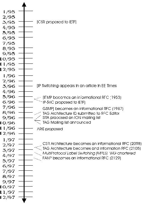
Figure 3 - Timeline for switching in IP up to formation of MPLS working group. *
Figure 4 - Scheduled verses actual working group goals *
Figure 5 - Signaling document roadmap *
Figure 6 - Encapsulation document roadmap *
Figure 7 - Architecture, framework and issues document road map *
Figure 8 - VPN, TE and OMP document roadmap *
Figure 9 - Separation of Routing and Forwarding *
Figure 10 - Partial deployment of Label Switching Routers *
Figure 11 - Forwarding decision tree *
Figure 12 - VC Merging avoiding cell interleaving *
Figure 13 - Label and Label Stack Manipulations *
Figure 14 - Per-platform Label Space *
Figure 15 - Effect of non-continuous LSPs between BGP peers *
Figure 16 - Comparison of tunneling encapsulation approaches *
Figure 17 - MPLS generic label format *
Figure 18 - Negotiation of stacked labels in LSP tunneling *
Figure 19 - Source Routing IP option encapsulation *
Figure 20 - ATM encapsulations of MPLS labeled packets *
Figure 21 - Frame Relay encapsulations of MPLS labeled packets *
Figure 22 - PPP encapsulation of MPLS labeled packets *
Figure 23 - MPLS (Network) Control Protocol for PPP (MPLSCP) *
Figure 24 - Ethernet encapsulations of MPLS labeled packets *
Figure 25 - Piggy-Back Labels in BGP *
Figure 26 - PATH Message Format *
Figure 27 - RESV Message Format *
Table 2 - Encapsulation Design Teams *
Table 3 - Framework and Architecture DesignTeams *
Table 5 - Signaling alternatives and applications *
Table 6 - RSVP-TE Error Codes and Values *
Table 7 - LDP General Message Types *
Table 8 - LDP/CR-LDP Status Codes *
Table 9 - LDP/CR-LDP (TLV) Objects *
You may be interested in this book because you are a Network Engineer, a Network Planner or Architect, or other person thinking about deploying MPLS in your own network. You may find this book interesting if you are a technical manager or an engineer thinking of implementing the technology in your products. You might be a student who has volunteered your time and energy to study another tough subject. Or you may simply have heard of the technology and are interested in seeing where reading up on it might take you.
It is possible that a person might pick this book off of a shelf - either at a bookstore, or in a technical library - with out ever having heard of the technology, but it is not very likely. MPLS is, after all, yet another member of the new generation of four-letter acronyms (ATM having fairly demonstrated that the age of original three-letter acronyms has passed) and will - therefore - not be of urgent interest to someone who has not even heard of it.
Finally, at the time that I am writing this book, there are no reasonably up to date detailed technical books on the subject and yet there are a lot of questions and general interest in this exciting new technology. The fact that you've read this far, indicates that you are one of the many people with questions about this new technology.
Hence, unless you're still convinced that MPLS is
the abbreviation for Minneapolis, the fact that you still have this book
in front of you indicates that you are likely to be someone who should
read it.
Jhilmil Kochar
Loa Andersson
Muckai K Girish of SBC Technology
Resources, Inc.
Radia Perlman
Randal T. Abler of the Georgia
Institute of Technology
Rob Blais of the University of
New Hampshire InterOperability Lab
Ron Bonica
Ross W. Callon
Thomas D. Nadeau of Cisco Systems,
Inc.
Tom Herbert
Walt Wimer of Marconi Communications
Their efforts did much to encourage me and help to improve the readability and accuracy of the work.
I also wish to thank co-workers who offered encouragement and support throughout the time I spent working on the book. I particularly want to thank Barbara Fox, Pramod Kalyanasundaram and Vasanthi Thirumalai (then of Lucent Technologies) and people I worked with at Zaffire, including Fong Liaw, George Frank, John Yu and Michael Yao.
Nobody helped quite as much as those closest to me. I offer a very special thanks to the members of my family who bore with me during the many crunch periods.
Finally, I wish to acknowledge the help and patience of the staff at Addison Wesley Longman, in particular: Karen Gettman, Mary Hart, Emily Frey and Marcy Barnes.
The most important example of a routing problem MPLS deals with today is Traffic Engineering. Traffic Engineering is the approach network operators typically use to equalize traffic loads across all devices in their network. Traffic Engineering may be done more easily using MPLS than it was being done previously.
The second most important routing problem that MPLS offers a solution to is support for Virtual Private Networks. MPLS may be used in a number of ways to provide for tunneling private network traffic across a public or backbone infrastructure.
The simplicity of the forwarding process offered by MPLS, however, makes it highly likely that there will be other - perhaps more important - applications for this technology in the future. In general, if one of the alternatives that is being considered in solving a network (or routing) problem is using a packet tunneling approach, MPLS is likely to be a useful solution for that problem.
I intended for this book to be a self-contained reference for MPLS technology. However, MPLS as a technology interacts with a large number of other technologies. Included in these interactions are various routing protocols, link-layer and - in theory at least - network layer technologies. I do not, for example, describe in this book the specifics of individual routing protocols except as they directly relate to MPLS. There are many good reference books on routing, network and link layer technologies.
This book provides an overview of the various technologies that led to the development of MPLS. A relatively high-level summary of the history of the development process is useful in understanding some of the choices made in that process. However, the goal in this book is to make the protocol itself understandable, so the focus is on the protocol details that resulted from the process of merging the various proposals; it does not perform a detailed analysis and comparison of each one. There are already books that do a good job of comparing at least the early proposals.
I based the material in this book on publicly available information. Statements made in this book can be verified by anyone wishing to do so. Of course, not all of the public information is consistent. In particular, for several topics that are completely unavoidable in a serious attempt to talk about label switching, it is not actually possible to distill a common conclusion from the available information - or, at least, it is not possible to do so objectively. Information presented by the various participants often contains obscure references to information that might or might not be well known - even if not publicly available - and was often starkly at odds with related information provided by others. An example of this would be the continuing debate over which signaling protocol is most useful under what circumstances.
Consequently, the goal of trying to make the multi-protocol label switching technology easily understandable (or - at least - more easily understandable) is slightly at odds with the goal of being fair and objective in discussing the results of the development of the technology standard. Too much fairness and objectivity would result in too much ambiguity.
I hope I've done a reasonably good job of achieving the understandability goal without compromising too much on fairness and objectivity.
As another example, I have used footnotes extensively. My hope - in so doing - is to make it possible for a reader to simply ignore the footnotes if they are not interested in a background or sidebar discussion, or where a particular comment or observation came from. Using footnotes in this way allows many readers somewhat greater ease in following the flow of the ideas being discussed. I know that some people are incapable of ignoring footnotes and other references and - for those people - I offer my heartfelt sympathy.
I have also tried to organize the chapters in such a way as to let each stand on its own in addressing a particular subset of MPLS functionality that might be of interest to people who are not as interested in other chapters. For example, people who are not interested in the history of MPLS, may skip chapter 2 entirely with little loss in understanding of - say - usefulness of MPLS for a specific network application. Of course, there will be people who are interested in all aspects of the technology, and - for those people - it is necessary to provide references that tie all of the pieces together. Therefore, I have set out with the dual goal of:
Chapter 1 describes the basics of the technology, using examples and providing an overview of the technical details. The main concepts discussed include what label switching and label swapping are and how they compare to routing, and what is required to signal labels.
Chapter 2 goes through the evolutionary process in which these revolutionary concepts developed. This brief history starts with a prehistory that touches on some of the problems people were trying to solve, some of the earlier proposals to deal with those problems and the way in which the problems themselves were evolving. Then the Chapter discusses the major proposals that actually drove the industry to develop one standard solution. Finally, the chapter provides a summary of the process of getting the standard to where it is now. Throughout this chapter, I provide time-lines and other charts in an effort to show how various efforts influenced each other.
Chapters 3, 4 and 5 take the reader a little closer to the technology and its relationship to the networking world. Chapter 3 explains how MPLS must interact with routing and the network and link layers in order to provide forwarding services at least as good as those that currently exist and the benefits MPLS is expected to provide within this framework. Chapter 4 details MPLS system architecture, including components, functions and operating modes. Chapter 5 shows where specific MPLS encapsulation and signaling approaches are most applicable. These chapters provide the ground work for more detailed discussion in the remaining chapters.
Chapter 6 provides detailed comparisons of MPLS and alternative approaches to solving the same problems. The reader should find out in this chapter how MPLS differs from other approaches and what the benefits are in using MPLS. In providing detailed comparison of alternatives, chapter 6 also shows how MPLS is supported over various technologies, including ATM, Frame Relay, Packet-On-SONET (POS) and Ethernet.
Finally Chapter 7 describes how services - such as QoS, Traffic Engineering and Virtual Private Networks - may be supported using MPLS.
Chapters 1-5 provide an overview of the technology while chapters 6 and 7 dig into the details.
Finally, an extensive glossary is provided with both acronym expansions and definitions of terms and phrases used in this book.
Currently, the two most important uses of MPLS are Traffic Engineering and Virtual Private Networks (in order of current importance). Although both can and are done currently using existing standard protocols, MPLS makes this simpler because it possible to take advantage of the separation of routing and forwarding to reduce or eliminate some of the limitations of routing.
In Traffic Engineering, for example, it is possible to specify explicit routes during the process of setting up a path such that data may be re-routed around network hot spots. Network hot spots (congestion points) develop as a result of the fact that routing tends to converge on selection of a single least cost path to each possible (aggregate) destination. Using an explicit route to direct significant portions of this traffic to parts of the network that are not selected by the routing process allows packets to bypass network trouble spots by (partially) ignoring routing.
It is also relatively simple to establish MPLS tunnels to allow transport of packets that would not otherwise be correctly routed across a backbone network - as is often necessary in support of Virtual Private Networks. A network operator can use MPLS to tunnel packets across their backbone between VPN sites making address translation and more costly tunneling approaches unnecessary.
MPLS is potentially useful for other applications. For example, MPLS is likely to be fully supported on Linux platforms used at small ISPs, businesses and residences to provide network access for multiple computers. Use of MPLS in forwarding packets using a software router may make a noticeable difference in the performance of the host being used as a router - for example allowing the Linux station to be used for network management, administrative and accounting applications and other purposes (such as playing Civilization or Pod Racer).
MPLS does not represent a merger of the link and network layers. Instead, MPLS interacts with both in a role as the arbitrator of layer two and layer three technologies. MPLS defines an encapsulation that resides between the network layer and link layer encapsulations, but - in some cases - it also defines values for significant field positions in the link layer encapsulation itself. This is the case for ATM and Frame Relay, for example. Thus the desirable features of link layer behavior may be achieved by:
MPLS is not expected to be an end-to-end solution. There is relatively little to gain from having host involvement in MPLS label allocation and use. In addition, MPLS scalability depends in part on limiting the scope of MPLS domains. Merging of labels becomes essential as the size of an MPLS domain increases and yet merging cannot extend all the way to end points - unless, for example, there is only one receiver for traffic in the Internet. Finally, use of labels in forwarding implies a strong trust relationship between systems allocating labels and other systems using them. Things being the way they are, that level of trust relationship does not currently exist end-to-end in the Internet.
Basic MPLS concepts expanded on in the first chapters are as follows:
1.2 - Label Swapping *
1.3 - Signaling Labels *
1.4 - References *
2.2 - TAG, ARIS and Other Proposals *
2.3 - A Working Group *
2.4 - Reference Key and References *
3.2 - Benefits *
3.3 - References *
4.2 - MPLS System Functions *
4.3 - MPLS Operating Modes *
4.4 - References *
5.2 - Encapsulation of Packets *
5.3 - Signaling *
5.4 - References *
Anything that two consenting routers do over a link layer is their
own business
- Tony Li
Of course, the lead car may use an arbitrarily complex code. The code may include where each car came from, where it is going, what it contains and how it is to be routed at each switching station. It may also describe who owns each item contained and whether or not those items have been inspected, have cleared customs or are insured. I'm sure you get the idea.
Much of this information may be needed if each switching station has to make an independent routing decision. For example, if there are goods on board that have not cleared customs, or otherwise been inspected, it is possible that some switching stations may be required to divert the railway cars to a location where this can take place. However, for more mundane railway cars and at many switching stations, the routing options are not so complicated and it is likely that many similar trains can be grouped into a class in which all class members are switched in the same way.
In fact, such a switching system can realize substantial savings in storage if it stores exactly that information about each class that it needs to identify members of that class. The system then determines class membership by examining the code provided by the lead car and searching for a "best fit" among the routing information it has stored.
To understand why this may be important, imagine that the automated switching system supports well over a hundred million (108) railway terminal stations. That would mean that storing routing information based solely on source and destination would require over 1016 route entries. Additional information that might be required to identify an individual route would further compound this complexity.
However, performing a "best fit" (or longest match, in routing parlance) search at every switching station and for every set of railway cars has its own costs. The code used by the lead car must be successively compared with code fragments (following a decision tree) looking for the first point at which it does not match a code fragment on any sub-branch (of the decision tree). In practical usage, multiple comparisons are required in every case.
To put this cost in perspective, imagine that I'm thinking of upgrading the automated switching system such that it can switch 20 million cars a second and I don't want to have cars side-tracked for an appreciable amount of time at every station.
In this case, I would want to reduce the time it takes to match the code for the lead car with a routing entry by as much as possible. One way to do that would be to replace the complex code we've been using with a shorter one that exactly matches a code associated with an individual route entry at each switching station. This is, in essence, what MPLS does.
Let's examine this analogy now and see how it compares to the general concept of routing and switching data packets.
In the analogy:
Most network layer data packets are pretty mundane, however, and are routed based on a network layer destination address at most network devices. This is a good thing because there are something like 100 million IP end stations in the Internet and thus there is a need to be able to group destination addresses into classes.
Aggregating route information using destination-based routing produces forwarding classes based on a network layer address prefix. Because not all prefixes will be the same length, routing decisions are typically based on a longest match ("best fit") algorithm. The need to perform multiple comparisons establishes the maximum speed at which routing decisions can be made and thus sets the maximum rate at which a given routing device can forward packets, for any particular device's processing speed.
The maximum speed at which I can forward packets determines the efficiency of my utilization of a particular line speed. For example, if my interface line speed is roughly 2.5 gigabits/second (corresponding to OC-48 SONET) and my packet size distribution is 64/200/1500 (minimum/average/maximum) bytes/packet, I can compute the approximate required packet-processing speed (for ~100 % utilization) as follows:
Smax = (2.5 * 109)/(64 * 8) @ 5 million packets/second Equation 1
Savg = (2.5 * 109)/(200 * 8) @ 1.5 million packets/second Equation 2
Smin = (2.5 * 109)/(1500 * 8) @ 200 thousand packets/second Equation 3
If I now want to introduce 10 gigabit/second line rates (corresponding to OC-192) into my network, I need to be able to increase my packet-processing rate to roughly 20 million packets per second (in order to handle a continuous stream of minimal packets).
In order to distinguish between forwarding based on longest match and forwarding based on exact match, many people refer to the former as routing and the latter as switching. That is a key distinction in the way I use these terms in this book.
Switching @ Bridging Equation 4
This comparison is useful to many people who are familiar with the differences in complexity in bridging and routing because it can help them to understand advantages that switching has to offer in comparison to routing.
In addition, there are technologies that have always been referred to as switching - for example, circuit-switching, ATM and Frame Relay. People familiar with these switching technologies generally associate switching with the idea of higher forwarding speeds. The higher forwarding speeds these technologies offer are, at least in part, due to the simplified forwarding made possible by using an exact match on a fixed length field. Unlike bridging and some other switching technologies, however, ATM and Frame Relay may exchange the values on which forwarding is based. For example, a Frame Relay DLCI is used in conjunction with an input interface to determine both the output interface and the new DLCI.
If a network device is able consistently to make forwarding decisions based on well-known bit positions in message headers, the process of making the decision is very simple. This is true regardless of the header to which this applies (whether it is a layer 2, layer 3 or higher layer). Values in these bit positions may be used as a control word that sets up a temporary channel from the interface on which the packet was received to the interface on which the packet is to be re-transmitted - thus switching the packet. A common approach for doing this is through the use of content addressable memory - the significant header data is used to access a data-record in high-speed memory that is then used to switch the data to the appropriate output interface. The data-record may also include replacement header information.
Switching is based on the ability to consistently determine how to forward packets from well-known bit positions in message headers.
Prior to the introduction of MPLS (and related proposals), the forwarding decision was a great deal more complicated for routing than it was for any switching technology. From the earliest generations, routers have been tasked with dealing with multiple paths across a network and, over time, multiple network layers and corresponding packet formats. Routing is also required to provide access to the global Internet (Internet) - i.e. to act as a gateway between a private network (intranet) and any and all other networks (extranets) - including the Internet. The Internet is orders of magnitude larger and more complicated than any currently existing bridged network segment.
Of course, there is a direct relationship between complexity of any task and the cost of acquiring and maintaining the equipment necessary in performing the task, i.e. -
Costacquire + Costmaintain@ K * Complexity Equation 5
From this, we can make an inference about the relative costs of bridging (or switching) and analogous routing functions. If the complexity of a routing function is orders of magnitude greater than the complexity of a bridging function, then the cost of the routing function (in terms of initial outlay and continuing operating costs) should be orders of magnitude greater than the cost of an analogous bridging function. That this is not always reflected in equipment prices is a fact that is attributable to at least some of the following factors:
Hence, routers and routing protocols have evolved - and continue to evolve - mechanisms for continuing to forward data. Most such mechanisms are based on using distributed route computation. At any given instance in time, a router is likely to believe it knows the right thing to do with a packet (thus avoiding dropping it as much as possible). However the "right thing to do" (as determined using route table information) is:
Since it is possible that the information used to make forwarding decisions is not consistent at all routers in any portion of the network, it is certain that data packets may take the wrong path and even loop. Some part of the forwarding decision process must be to determine if data is looping too much (consuming too many network resources) - and this typically is done on a packet by packet basis (using TTL for example).
Routing technologies, consequently, rely on loop mitigation approaches. Use of TTL, for example, prevents packets from consuming more than a fixed amount of network resources (on a per-packet basis that is).
Switching technologies construct a simplified network topology that restricts the paths available for forwarding thus making looping impossible. Prior to constructing (or restricting) forwarding paths, switching technologies typically do not forward data packets. Consequently, a transient in a switched network will usually result in a total loss of use of the network until the new topology is completely determined.
Bridging technologies, for example, use the spanning tree algorithm to construct a connected, loop free, forwarding tree. This is accomplished by disabling forwarding using certain interfaces at each bridge. Hence, looping data is avoided by choosing not to use some network resources.
Other switching technologies use a connection-oriented approach based on virtual circuits that are similarly loop free. Consequently, switches do not have to check to see if packets are looping since packets follow a path that has been determined to be loop free during the setup process. Use of virtual circuits does not necessarily guarantee equal use of network resources, however, and it is disruptive to move a virtual circuit from one path to another in an attempt to redistribute traffic.
Routers generally attempt to detect that a loop exists during the process of forwarding data, while switches generally attempt to eliminate loops prior to forwarding data.
Until very recently, routers in enterprise (private) networks were required to support several network (or higher) layer protocols. In particular, IPv4, IPX and Appletalk were in use in many corporate networks. Recent trends have been toward exclusive use of IPv4. Ideally, all networks would eventually switch to exclusive use of IPv4, however, IPv6 is looming on the horizon.
One solution used in the past relied on a simplistic optimization approach - optimize for the dominant (or normal) case only. This meant that forwarding of IPv4 packets, with no IP options in use, would be optimized while forwarding of other network layer packets, or IP packets with options specified, might be performed in a substantially sub-optimal way. Because of the possibility of network layer transitioning from IPv4 to IPv6 at some point in the future it is very likely that many routers will need to support both versions of the Internet Protocol. Consequently, people who build routers are less willing to assume that it is sufficient to optimize packet processing for only one network layer protocol.
An efficient switching solution to the problem of having a variety of network layer protocols is to perform a forwarding decision on the basis of information that is not dependent on the network layer - at least on a per-packet basis. For instance, switches that use virtual circuits can establish virtual circuits for the purpose of switching specific sets of network layer packets along a path. If the path is determined during virtual circuit setup, using the same route determination process that would otherwise be applied on a per-packet basis, then these switches only need optimize the process of forwarding along the virtual circuit. The actual forwarding process is thus independent of the network layer used in making a route determination.
Routers decide how to forward each packet by determining the route for the packet from the L3 (network layer) header and the router's route table. Switches decide how to forward each packet using a function that is separate from the process of determining the route for packets having any particular L3 header.
In addition, routers frequently serve as "gateways" between network domains - imposing filtering, security and other complicating factors on the already complex routing task. The gateway function is an essential part of access to the Internet.
The additional complexity associated with domain boundaries affects both the process of forwarding data and the process of computing routes. Data forwarding is impacted since filtering, address translation or header manipulation impose requirements to look more closely at the packets being forwarded. The process of computing routes is affected because the information shared across domain boundaries by routing protocols may be limited by policy considerations or limitations in the ability to import routes and these limitations may lead to inaccurate data affecting route computation.
The net effect of the combination of these two complicating factors is that it is possible for the policies affecting forwarding and route computation to be inconsistent. This increases the likelihood of incorrectly forwarding data packets - leading to packet loss and potentially lost network connectivity.
Switching technologies such as Frame Relay and ATM had a significant impact on the distinction between bridging and routing. ATM, for example, uses routing for Virtual Circuit (VC) setup and switching of actual data packets. These switching technologies represented the first industry-wide attempt to uniformly separate route determination from forwarding in data networks.
The general approach, suggested by the ATM specific paradigm, is to use routing protocol exchanges, router configuration information and routing decisions to setup virtual connections for streams of data. In the MPLS analog, a virtual connection for a specific data stream is established across some subset of network devices based on the routing decisions these devices would make for the actual data in those streams. Labels corresponding to ATM Virtual Path and Channel Identifiers (VPI/VCI or VPCI) locally identify the virtual connection. Once a virtual connection is thus established, the data packets may be forwarded based on the labels assigned - allowing for a high-speed forwarding implementation similar to ATM.
Unlike ATM, however, the label-switching approach is generally applicable to a number of network technologies, does not always require fragmentation of data packets into cells and allows direct use of native routing information and technology. Label Switching is the process of making a simplified forwarding decision based on a fixed length label and this label can be included in a Frame Relay DLCI, an ATM VPI/VCI or at the head of an MPLS shim header in other technologies.
Not all switching technologies modify the value used in making a forwarding decision. Circuit switching (for example, in voice telephony) and transparent bridging (in data networking) are instances that do not modify the value used to decide how to forward information. The trouble with approaches like these is that the values used have to be established as unique for all members of a network using this common technology. In other words, the labels used are more than locally significant.
Label Switching relies on Label Swapping to preserve the local significance of a label. In addition to enabling the switching function, the label in a label-encapsulated data packet received on an input interface is used to determine the label that will be used in transmitting the altered data packet on an output interface. This is highly analogous to VPI/VCI switching in ATM, for example, in which the input interface and VPI/VCI determines the output interface and VPI/VCI. Local significance is important in reducing the complexity of the process of negotiating labels since it is only necessary to know that the label is locally unique and the label does not have any non-local meaning.
In addition to possibly swapping the input label with an output label, one or more labels may be popped from the label stack of the received data packet and one or more labels may be pushed on to the label stack for the packet to be transmitted. In fact, label swapping itself may be logically generalized as the degenerate case of a pop (one or more labels) and push (one or more labels) in which exactly one label is popped and exactly one pushed. Pushing and popping of labels (adding/removing one or more labels) is discussed in greater detail in the Label Stack Manipulation portion of section 4.2 - MPLS System Functions.
Label swapping effectively establishes the Label Switching Router (AKA Label Switch Router or LSR) as a media end-point, defining the local scope of the label being swapped and, thus, the domain within which the label is significant and must be unique. This limitation in the scope of a label greatly increases the scalability of label switching since any label need only be unique between the LSR that allocates it and the LSR that prepends it to a packet.
The significance of a label received at an input interface is that it is used to:
Figure 1 - Label Switching Routers with multipoint to multipoint connectivity
Although the significance of a label might be established via configuration (or provisioning), this will prove to be an onerous task if large numbers of Label Switched Paths (LSPs) are required. In addition, this will not allow for the dynamic changes in routes currently supported in routed networks. Finally, as the amount of configuration increases, the probability of configuration error approaches certainty.
Consequently, label switching requires mechanisms for signaling, or distributing, labels within a domain of label significance. In general, LSRs that share knowledge of the significance of a set of labels are adjacent - at least within the context of the signaling mechanisms used to distribute those labels. These mechanisms must ensure that label significance is consistent both among various adjacent LSRs and with respect to each label's meaning at each LSR.
Figure 2 - Adjacency among Label Switching Routers
Consistency relative to a label's meaning is slightly different from simply keeping each adjacent LSR on the same page with label and forwarding information. The information used by the routing function at each LSR is subject to constant change - not only in terms of how a particular stream of data is forwarded, but also in terms of whether or not a particular message is part of that stream. Because of this it is necessary that adjacent LSRs be able to negotiate more or less labels as needed to support changing forwarding requirements.
An example of this is when routes are aggregated and the aggregate is associated with a single label. If a subset of the routes thus aggregated subsequently change (such that they diverge from the remaining routes associated with the aggregate label), the LSRs will need to negotiate one or more new labels.
The simplest way to ensure that any label is consistent among adjacent LSRs and consistent with its meaning relative to specific forwarding, is to piggy-back the labels being distributed using the same messages the routing function at each LSR uses to establish forwarding. In order to piggyback labels, however, it is necessary that forwarding information be shared between routers via protocols meeting these conditions:
To illustrate the first point, imagine a protocol consisting of message exchanges between LSRs that may or may not be adjacent. Labels attached to such messages will not be useful in cases where the LSRs are not adjacent as the label negotiated in this way will need to be interpreted or assigned by devices not participating in the negotiation.
Note that the adjacency here is in terms of how the labeled messages are transported from one LSR to another. If the labeled packets are L2 encapsulated, the presence of one or more transparent bridges between two LSRs does not affect their adjacency. In the same way, an LSP may be used to provide adjacency, as may any of several other tunneling approaches which allow transparent packet transport.
In Figure 2 above, if LSRs 2, 3 and 4 are using protocol XYZ and LSR 1 is not, protocol XYZ cannot be used to piggy-back labels between LSRs 2 and 4 unless a more direct adjacency is established between these two devices.
Similarly, there must be a contextual mapping between the logically adjacent peers in both the piggyback protocol candidate and MPLS contexts. If routers are adjacent with respect to a piggy-back candidate protocol but not adjacent with respect to MPLS, the labels which might be piggy-backed on the candidate protocol would be meaningless in the MPLS context since intervening LSRs would be unable to interpret (and properly forward packets using) these labels. In the same way, adjacent LSRs can only piggyback label distribution on protocols in which all adjacent LSRs participate and are logically adjacent. Otherwise, some of the adjacent LSRs would not be aware of the labels being distributed.
Let's use BGP as an example to illustrate this. Labels may be negotiated using BGP messages to piggy-back label assignments from one BGP peer to another. But for these labels to be useful, the peers participating in the negotiation must be either physically adjacent, or they must be logically adjacent via an LSP between them. If they are not directly adjacent, and there is not a continuous LSP between them, any labels negotiated between them will have no meaning at some point between the two peers. In this example, two adjacent BGP speakers are not logically adjacent LSRs.
The protocol being considered as a candidate for piggy-back distribution of MPLS labels should have defined mechanisms or protocol extensions to allow the labels to be transported via intervening devices in the event that protocol peers are not physically adjacent. It would not do, for instance, if the messages carrying MPLS labels were being discarded as incompatible with the base protocol in intermediate systems.
Protocol extensions used to carry labels must be defined for carrying the appropriate type of label as well. For example, a candidate piggy-back protocol needs to be able to include an ATM VPI/VCI in order to establish LSPs for use with ATM links.
Under circumstances in which no candidate protocol for piggyback distribution exists and is acceptable, labels must be distributed using a protocol specifically provided for that purpose. A specific label distribution protocol is also needed to permit negotiation of label parameters and provide ACK/NAK responses to label assignments where piggy-back protocols do not themselves provide mechanisms for doing these things.
What MPLS buys us is the ability to make a routing decision one time
and a series of switching decisions along an LSP.
In the simplest case, this is what MPLS allows routers to do - via signaling.
[3rd Computer Networks] - Third Edition, Computer Networks, Andrew S. Tanenbaum, Prentice Hall, 1996.
[BGP REFLECTORS] - BGP Route Reflection An alternative to full mesh IBGP, Tony Bates and Ravishanker Chandrasekeran, RFC 1966
[Interconnections] - Interconnections, Bridges and Routers, Radia Perlman, Addison Wesley, 1992.
[MPLS-Drafts] - Various, http://www.ietf.cnri.reston.va.us/ids.by.wg/mpls.html
[OSI] - OSI, A Model for Computer Communications Standards, Uyless Black, Prentice Hall, 1991.
[OSPF] - OSPF, Anatomy of an Internet Routing Protocol, John T. Moy, Addison Wesley Longman, 1998
[SONET] - SONET/SDH - A Sourcebook of Synchronous Networking, C. Siller and M. Shafi, editors, IEEE Press, 1996.
In the real world, outcomes don't just happen. They buildup gradually
as small chance events become magnified by positive feedbacks
- Dr. Brian Arthur
A thorough discussion of a technology is not truly complete without at least a summary of the history that went into making it. However, this chapter is essentially parenthetical. If you are not interested in the history of MPLS and how it developed out of a miasma of related technologies, skipping this chapter entirely will not prevent you from understanding the remaining chapters of this book.
In retrospect, there were disconnects in the process of defining both Switched Virtual Circuits (SVCs) and Traffic Management in ATM and the possibility of using these services in IP. These disconnects are not hard to understand for those people who were involved in the process. They were largely because of changes in market and product development directions stemming from the chaotic influence of market feedback. Similar feedback processes were involved in the standardization process as well. Where things ended up is not where things looked like they were going to end up at various stages in the process.
For example, LAN Emulation ([LANE]) was developed because of a then widespread belief that ATM to the desktop was the future technology direction. LANE defined a client-server architecture and service implementation to support use of ATM switches in a bridged network. Focus for LANE was on interworking with the dominant L2 technologies - specifically IEEE standards 802.5 (Token Ring) and 802.3 (nearly identical to, and usually thought to include, Ethernet) - in order to support L2 technologies generally. Work in developing LANE was coordinated with continuing efforts in the IEEE through the occasionally heroic efforts of people participating in both efforts.
Multi-Protocol Over ATM (MPOA) was developed in turn as an effort to extend the thinking (if not at all times the technology) used in developing LANE to be useful in a routed ATM network. MPOA also defined a client-server architecture and service implementation - however MPOA applies to routing in all-ATM networks. MPOA focused on use of the Next Hop Resolution Protocol (NHRP), then being defined in the IETF working group Routing Over Large Clouds (ROLC). NHRP was intended to solve some of the problems then known to exist with Classical IP and ARP over ATM (CLIP) and - for this reason - was regarded by some to be the next generation CLIP version. Work in developing MPOA was coordinated with ongoing efforts in the IETF in the same way that similar coordination occurred in LANE.
While MPOA represented a major attempt to reconcile differences between what had developed as two separate routing models, one for ATM and one for IP, its proponents were not at all in agreement about what the target model should be. Many people saw that the NHRP architecture offered a well understood way to separate the route determination and forwarding functions, but the effort within the MPOA was split on how best to take advantage of this. Part of the effort centered around use of NHRP's client-server architecture to develop a virtual router architecture while part of the effort centered around trying to define extensions to the NHRP protocol specific to ATM that would allow ATM-native traffic management features to be used in forwarding IP packets.
Of course, if the routing overhead in any particular implementation is negligible, this aspect of the use of NHRP (and, consequently, MPOA) is not as important. However, implementations in which this was the case tended to be regarded as either largely theoretical or prohibitively expensive at the time these considerations were being made.
The value of this approach is sensitive to the number of ATM switches that are not also routers. Obviously, if every ATM switch is a router, then there will be no mismatch between ATM physical connectivity and the routing topology. If only one out of every ten ATM switches is also a router, then some degree of topological mismatch may be unavoidable. At the time these things were being considered, it was generally accepted that adding routing function to every ATM switch would be expensive - especially if one is trying to avoid the routing overhead at the same time.
NHRP - by itself - does nothing to address this problem. Unless the protocol's usage is restricted in some way, NHRP cannot provide connectivity between ATM end-stations in a cloud larger than was the case with a LIS in CLIP. Thus NHRP (and MPOA) is effective only when it is used to establish connectivity to a restricted subset of all end-stations in any one ATM cloud. Such a restriction could be based on whether or not the connection is associated with some level of service assurance, whether or not there is a topological mismatch associated with the normally routed path, or both.
Neither the ROLC group (and its successor - ION) nor the MPOA working group embarked on an effort to define signaling mechanisms and mappings between either IntServ or DiffServ like Quality of Service (QoS) and ATM signaling parameters. This effort was the responsibility of the corresponding work groups within the IETF. While a lot has been done in this area to date, the lack of progress at the time that NHRP was approaching becoming a Proposed Standard in the IETF made it hard for implementers to provide for inclusion of QoS parameters in NHRP messages.
Another issue with CLIP was the delay caused by the need to perform address resolution in order to determine the address of the ATM local destination for any particular IP destination address. This issue exists also when using NHRP - and is potentially worse because resolution requests may be forwarded multiple hops before an appropriate address resolution response can be returned. Implementations that attempt to compensate for this factor by "learning" ATM address associations would interfere with the efficacy of those implementations trying to restrict ATM connectivity.
The routing decision on a per-packet basis can be avoided - in ATM switches - if there is some way to associate the input interface and VPI/VCI of ATM cells received with output interface and VPI/VCI to be used on forwarding them. Typically this cannot be done in any interesting ATM switch router because VPI/VCI values on an incoming and outgoing interfaces will correspond to the end-stations or routers connected to this interface - rather than the source or destination of the IP packets being carried in the cells.
Folks at Toshiba recognized that - if a signaling protocol is used to establish new VPI/VCI values for specific flows of IP packets arriving at an input interface - then these special values could be bound to corresponding VPI/VCI values at an output interface. In this way a cell arriving with one VPI/VCI value would be switched at the ATM layer to the appropriate output interface and would be assigned the correct VPI/VCI for forwarding to the next hop router or end-station. Yasuhiro Katsube, Ken-ichi Nagami and Hiroshi Esaki submitted their Internet Draft "Router Architecture Extensions for ATM: Overview" to the IETF describing this idea at that time. In their draft, they proposed alternative signaling protocols for use and described how a Cell-Switching Router (CSR - [CSR-T]) would interwork with ATM switches, other types of ATM-switch routers and end-stations.
The basic idea was that the majority of packet flows would still be processed using the routing function but that specific flows would be forwarded at the ATM layer based on use of an additional signaling protocol. Flows involving special handling and flows consuming higher numbers of VCs would fall in two categories: default or dedicated VCs. Default VCs could be setup - for example - by using CLIP. Dedicated VCs would be setup using some other (in-band or out-of-band) signaling protocol. Protocols initially proposed included STII and RSVP (ReSerVation Protocol). Subsequently, the same authors, along with four of their colleagues at Toshiba Research, proposed a specific protocol - Flow Attribute Notification Protocol ([FANP]).
Kenji Fujikawa, of Kyoto University, published an Internet Draft [IP-SVC] in May 1996, proposing a lightweight ATM signaling replacement for use within an ATM LIS. This was intended to replace CLIP as a complement to - and thus an extension of - the earlier CSR proposal. While interest in this proposal continued for some time (it later became know as [PLASMA]), it has not become part of the mainstream effort in later MPLS standardization and signaling protocol development.
Up to this point, existing proposals relied on use of native ATM signaling to establish at least default ATM virtual circuits. Ipsilon Networks, Inc. suggested a new approach - abandon the currently defined signaling in ATM and introduce a new signaling protocol to be used to manage IP flows. Ipsilon proposed a flow management protocol (Ipsilon's Flow Management Protocol - [IFMP]) for use in establishing (for example) VPI/VCI values to be used by neighboring ATM switches for specific IP flows. The assumption in this approach is that IP switches would forward IP packets between IP hosts and routers using default encapsulation until a flow is detected and a redirection message sent. Once an IP switch sent a redirection message - including a new encapsulation value (VPI/VCI in ATM) - the neighboring host, router or IP Switch would forward packets belonging to the defined flow using the newly defined encapsulation. Use of the new data-link layer encapsulation - which would be locally unique to a specific flow - would allow a neighboring router to forward IP packets associated with that flow at the data-link layer.
The Ipsilon approach had the advantage - relative to Toshiba's CSR proposal - of being potentially able to reduce the default forwarding load by a larger percentage of all IP packets being forwarded at any particular IP router. Unlike CSR, however, IFMP depended to a large degree on flow detection at each IP routing node in a network composed of IFMP-participating IP routers. This could result in significant overhead in IP packet processing in the default-forwarding mode and required implementations to pay attention to the activity of IP packets even in redirected flows.
In order to avoid scale issues associated with both CLIP and NHRP, IFMP-participating implementations would need to use flow detection algorithms aimed at detecting a relatively small percentages of the total number of IP flows. In order to minimize the over-all impact on IP forwarding, however, this small percentage of flows would need to carry a significant majority of the traffic. Based on data available from researchers at FIX-WEST, folks at Ipsilon proposed several approaches for detecting flow that would result in low flow count to redirected packet ratios.
Issues discussed relative to the Ipsilon approach were similar to those raised with CLIP and NHRP earlier:
In late March, 1996, Greg Minshall (of Ipsilon Networks, Inc.) observed that greater scalability was achievable through the use of ATM switches that could merge ATM cells at the frame level from multiple input VPI/VCIs onto a single output VPI/VCI. This would have to be done without interleaving the cells associated with any particular frame with cells from other frames in the same output VPI/VCI. But it could be accomplished using a state variable - thus eliminating the need to actually assemble the frame at the IP layer. This simple observation may have led to the most significant contribution in many of the ensuing IP switching proposals.
2.2 - TAG, ARIS and Other Proposals
In the last few months of 1996, several new proposals popped up either on the ROLC and ION mailing lists, or on the tag-switching mailing list set up by Cisco Systems, Inc. to discuss their proposal or on the ION mailing list. Included among these were the following:
Cisco Systems, Inc. and IBM Corporation each publicly announced their own versions of IP Switching late in 1996. Cisco announced the formation of a tag-switching discussion list and availability of tag-switching architecture [TAG-ARCH] and tag distribution protocol specification [TDP] documents in September. IBM posted an Internet draft - Aggregate Route-based IP Switching [ARIS] - in November. Cisco posted their first versions of tag switching over ATM and tag encapsulation in time for presentation at December Birds Of a Feather (BOF) meeting [IETF-37].
Essential differences between the TAG and ARIS proposals were:
Between the TAG and ARIS proposals, another proposal was discussed on the Internetworking Over NBMA (ION) mailing list. This proposal - referred to at the time as Switching IP Through ATM ([SITA]) - suggested a simplistic configuration based approach to supporting IP packet switching over ATM. It also suggested a variant of VP merging as later proposed in ARIS. In this proposal, ATM VCIs would be configured based on the egress for a specific class of packets while VPIs would be configured based on the ATM ingress that first classified each packet. This proposal was updated in early November, but was subsequently dropped by its author.
While there had been an earlier attempt to establish a tag-switching forum, with the advent of TAG, ARIS and other proposals, it was clear that the possibility of developing a standard packet switching approach needed to be considered. Hence there was a Birds Of a Feather (BOF) meeting in December 1996. The result of this meeting was the decision to form an IETF working group - which would later come to be called Multi-Protocol Label Switching (MPLS).
While the decision was made - in December 1996 -
to form a working group to develop a standard approach for Switching IP,
the MPLS working group was not actually formed until March 3, 1997.
Figure 4 above shows both the projected and the actual schedule for delivery of MPLS specifications. In this figure, it is apparent that original projections were based on unbridled optimism in most cases. On average, the delay between hoped for and actual delivery was more than a year.
To describe in detail how each of the various drafts developed by the MPLS working group evolved would take perhaps hundreds of pages and would - therefore - not be of use to most people. In subsections of this chapter, however, I have attempted to capture pictorially how the numerous drafts were interrelated and provide a very topical summary of the evolution process.
One general qualification must be made on this effort - I have tried to show reasonably strong links between drafts on related topics, based on specific acknowledgement, consensus of the working group (both on the mailing list and in working group meetings) or from participants in the process. It is necessary to acknowledge that other associations probably exist and it is fair to admit that all drafts publicly issued at any given point may have had direct or indirect impact on the ideas and material that is included in subsequent drafts.
In addition, many of the drafts associated with development of MPLS signaling protocols were put forward by individual contributors or multiple contributors from individual organizations. Each section lists any design teams that are notable exceptions to this rule (where members of more than one organization cooperated to develop one or more drafts).
Note that the tables represent the affiliations of individuals contributing to each effort during the period of active work. For that reason, many of the individuals listed may be listed as having different affiliations in different efforts. Many have different affiliations now than during any part of the MPLS protocol development effort.
|
|
|
|
| LDP Design | Loa Andersson | Ericsson
Telecom,
Bay Networks, Nortel Networks |
| Paul Doolan | Ennovate Networks | |
| Nancy Feldman | IBM | |
| Andre Fredette | Bay
Networks,
Nortel Networks |
|
| Bob Thomas | Cisco Systems | |
| CR-LDP Design | Osama
Aboul-Magd,
Loa Andersson, Peter Ashwood-Smith, Andre Fredette, Bilel Jamoussi |
Nortel Networks |
| Ross Callon | Ironbridge Networks | |
| Ram
Dantu,
Liwen Wu |
Alcatel | |
| Paul Doolan | Ennovate Networks | |
| Nancy Feldman | IBM | |
| Joel Halpern | Newbridge Networks | |
| Juha Heinanen | Telia Finland | |
| Fiffi
Hellstrand,
Kenneth Sundell |
Ericsson Telecom | |
| Timothy Kilty | Northchurch Communications | |
| Andrew Malis | Ascend Communications | |
| Muckai Girish - | SBC Technology Resources | |
| Pasi Vaananen | Nokia Telecommunications | |
| Tom Worster | General DataComm | |
| MPLS-RSVP Design | Bruce
Davie,
Yakov Rekhter, Eric Rosen |
Cisco Systems |
| Arun Viswanathan | Lucent Technologies | |
| Vijay
Srinivasan,
Steven Blake |
IBM | |
| RSVP-TE Design | Daniel Awduche | UUNET Worldcom |
| Lou Berger | Fore Systems | |
| Der-Hwa
Gan,
Tony Li |
Juniper Networks | |
| George Swallow | Cisco Systems | |
| Vijay Srinivasan | Torrent Networks | |
| Loop Prevention Design | Yoshihiro Ohba, Yasuhiro Katsube | Toshiba |
| Eric Rosen | Cisco Systems | |
| Paul Doolan | Ennovate Networks |
At this same time, a concern was raised about potential confusion of state machine interactions between LDP implementations using different control and label allocation modes in setting up LSPs. This was of particular concern because of the separation of signaling of explicit routes from the base Label Distribution Protocol specification. The working group established a draft ([LDP-State]) on LDP state machines for LSP setup to provide information on these interactions.
Both LDP and CRLDP drafts reached a state of relative completion in late 1999 and [LDP-State] entered working group last call toward the end of 1999. With the exception of modifying the procedures in appendices (to support non-merging LSPs) in the LDP specification, all LDP related drafts received only minor editing changes through out the year 2000.
Encapsulation and Related Draft Development
|
|
|
|
| PPP/Ethernet Encapsulation | Eric
Rosen,
Yakov Rekhter, Daniel Tappan, Dino Farinacci |
Cisco Systems |
| Tony Li | Juniper Networks | |
| Alex Conta | Lucent
Technologies,
3Com |
|
| MPLS-ATM Design | Bruce
Davie,
Jeremy Lawrence, Keith McCloghrie, Yakov Rekhter, Eric Rosen, George Swallow |
Cisco Systems |
| Paul Doolan | Ennovate Networks | |
| MPLS-FR Design | Alex Conta | Lucent Technologies |
| Paul Doolan | Cisco
Systems,
Ennovate Networks |
|
| Andrew Malis | Ascend
Communications,
Lucent Technologies |
Two exceptions - shown in Figure 6 - are:
Framework, Architecture and Other General Draft Development
|
|
|
|
|
|
|
Cascade
Communications,
Ascend Communications, Ironbridge Networks |
|
|
Cisco
Systems,
Ennovate Networks |
|
|
|
|
|
|
|
Bay
Networks,
Nortel Networks |
|
|
|
|
|
|
|
IBM,
Lucent Technologies |
|
|
|
|
|
|
|
Lucent Technologies |
|
|
|
Cascade
Communications,
Ascend Communications, Ironbridge Networks |
MPLS Architecture, Framework and three applicability statements ([CR-LDP-App], [LDP-App] and [RSVP-TE-App] reached effective completion in the second half of 1999.
VPN, TE and OMP Draft Development
There were a number of attempts to kick-start an effort to include standardization of a Virtual Private Network (VPN) support approach in the MPLS working group as well as in the IETF in general. The main reason why the majority of the VPN proposals that came forward were tabled is that it was felt that the requirements for VPN functionality were a subset of the requirements for Traffic Engineering (TE). Exceptions were a proposal to support VPNs over MPLS using BGP ([BGP-MPLS-VPN]) and a proposal for a standard VPN identifier format ([VPN-ID]). Both of these proposals are now RFCs.
Traffic Engineering requirements ([TER]) was the draft that energized much of the work in the MPLS working group from mid 1998 through late 1999. This draft - endorsed as it was by a major user of networking equipment - very quickly became the center-piece for virtually all efforts in signaling and other areas of MPLS development. This draft became an RFC in the second half of 1999.
Though there was genuine interest in it from several IETF working groups, the author of the work on Optimized Multipath was its primary driver in the MPLS working group. However, there was no consensus that there was a need to define anything in an MPLS context and this draft was allowed to expire.
2.4 - Reference Key and References
A note on the following references: the references listed in this section are divided into two categories:
Reference Key for Figures in this Chapter
Table 4, below, provides Key expansion for reference keys used in this chapter. Note that Internet Drafts are by nature "work in progress". Listing Internet Drafts here is for historical purposes and is not intended to indicate that the listed Internet Drafts are useful as reference material in determining how these ideas are actually implemented or should be implemented.
|
|
|
|
|
|
| [ARIS] | 0basic
0overview |
9/1996
3/1997 |
R. Boivie,
N. Feldman, A. Viswanathan, R. Woundy |
ARIS:
Aggregate Route-Based IP Switching
draft-woundy-aris-ipswitching-00 and draft-viswanathan-aris-overview-00 |
| [ARIS-S] | 0 | 3/1997 | N. Feldman,
A. Viswanathan |
ARIS
Specification
draft-feldman-aris-spec-00 |
| [BGP-MPLS-VPN] | 0
1 2547 0 1 2 |
11/1998
12/1998 3/1999 3/2000 5/2000 7/2000 |
E. Rosen,
Y. Rekhter, T. Bogovic, R. Vaidyanathan, S. Brannon, M. Morrow, M. Carugi, C. Chase, T. Wo Chung, J. De Clercq, E. Dean, P. Hitchin, M. Leelanivas, D. Marshall, L. Martini, V. Srinivasan |
BGP/MPLS
VPNs
draft-rosen-vpn-mpls-00 and 01, RFC2547 and draft-rosen-rfc2547bis-00, 01, 02 |
| [CLIP] | 1577
2225 |
1/1994
4/1998 |
M. Laubach | Classical
IP and ARP over ATM
RFC1577 and RFC2225 |
| [COCIFO-ATM] | 0 | 10/1994 | H. Esaki,
K. Nagami, M. Ohta |
Connection
Oriented and Connectionless IP Forwarding Over ATM Networks
draft-esaki-co-cl-ip-forw-atm-00 |
| [CR-LDP] | 0
1 2 3 4 |
1/1999
2/1999 8/1999 9/1999 7/2000 |
B. Jamoussi (Ed.) | Constraint-Based
LSP Setup using LDP
draft-ietf-cr-ldp-00, 01, 02, 03, 04 |
| [CR-LDP-0] | 0 | 10/1998 | L. Andersson,
A. Fredette, B. Jamoussi, R. Callon, R. Dantu, P. Doolan, N. Feldman, M. Girish, E. Gray, J. Halpern, J. Heinanen, T. Kilty, A. Malis, K. Sundell, P. Vaananen, T. Worster, L. Wu |
Constraint-Based
LSP Setup using LDP
draft-jamoussi-mpls-cr-ldp-00 |
| [CR-LDP-APP] | 0
0 1 |
8/1999
9/1999 7/2000 |
G. Ash, M.
Girish,
E. Gray, B. Jamoussi, G. Wright |
Applicability
Statement for CR-LDP
draft-jamoussi-mpls-crldp-applic-00 draft-ietf-mpls-crldp-applic-00 and 01 |
| [CSR] | 2098 | 2/1997 | Y. Katsube,
K. Nagami, H. Esak |
Toshiba's
Router Architecture Extensions for ATM: Overview
RFC2098 |
| [CSR-ARCH] | 0 | 12/1997 | Y. Katsube,
K. Nagami, Y. Ohba, S. Matsuzawa, H. Esaki |
Cell
Switch Router - Architecture and Protocol Overview
draft-katsube-csr-arch-00 |
| [CSR-T] | 0 | 3/1995 | Y. Katsube,
K. Nagami, H. Esaki |
Router
Architecture Extensions for ATM: Overview
draft-katsube-router-atm-overview-00 |
| [ECN] | 0 | 6/1999 | K. Ramakrishnan,
S. Floyd, B. Davie |
A Proposal
to Incorporate ECN in MPLS
draft-ietf-mpls-ecn-00 |
| [ENCAPS-DT] | 0
1 2 3 |
11/1996
3/1997 6/1997 7/1997 |
E. Rosen,
Y. Rekhter, D. Tappan, D. Farinacci, G. Fedorkow, T. Li, A. Conta |
Label
Switching: Label Stack Encodings
draft-rosen-tag-stack-00, 01, 02, 03 |
| [Encapsulation] | 0
1 2 3 4 5 6 7 8 3032 |
11/1997
2/1998 7/1998 9/1998 4/1999 8/1999 9/1999 9/1999 7/2000 1/2001 |
E. Rosen,
Y. Rekhter, D. Tappan, D. Farinacci, G. Fedorkow, T. Li, A. Conta |
MPLS
Label Stack Encoding
draft-ietf-mpls-label-encaps-00, 01, 02, 03, 04, 05, 06, 07, 08 and RFC3032 |
| [ETR] | 0
1 |
2/1999
6/1999 |
H. Hummel,
S. Loke |
Explicit
Tree Routing
draft-hummel-mpls-explicit-tree-00 and 01 |
| [Exp-Rt] | 0 | 11/1997 | B. Davie, T.
Li,
E. Rosen, Y. Rekhter |
Explicit
Route Support in MPLS
draft-davie-mpls-explicit-routes-00 |
| [FANP] | 2129 | 11/1996 | K. Nagami,
Y. Katsube, Y. Shobatake, A. Mogi, S. Matsuzawa, T. Jinmei, H. Esaki |
Toshiba's
Flow Attribute Notification Protocol (FANP) Specification
RFC2129 |
| [Fast-Reroute] | 0
1 2 3 4 |
6/1999
6/1999 12/1999 3/2000 5/2000 |
D. Haskin,
R. Krishnan |
A Method
for Setting an Alternative Label Switched Paths to Handle Fast Reroute
draft-haskin-mpls-fast-reroute-00, 01, 02, 03, 04 |
| [FLIP] | 1954 | 5/1996 | P. Newman,
W. Edwards, R. Hinden, E. Hoffman, F. Liaw, T. Lyon, G. Minshall |
Transmission
of Flow Labelled IPv4 on ATM Data Links Ipsilon Version 1.0
RFC1954 |
| [Framework] | 0
1 2 3 4 5 |
5/1997
7/1997 11/1997 6/1999 7/1999 9/1999 |
R. Callon,
N. Feldman, A. Fredette, G. Swallow, P. Doolan, A. Viswanathan |
A Framework
for Multiprotocol Label Switching
draft-ietf-mpls-framework-00, 01, 02, 03, 04, 05 |
| [IFMP] | 1953 | 5/1996 | P. Newman,
W. Edwards, R. Hinden, E. Hoffman, F. Liaw, T. Lyon, G. Minshall |
Ipsilon
Flow Management Protocol Specification for IPv4 Version 1.0
RFC1953 |
| [IP-MCAST] | 0
1 2 0 1 |
8/1998
2/1999 5/1999 6/1999 5/2000 |
D. Ooms,
W. Livens, B. Sales, M. Ramalho, A. Acharya, F. Griffoul, F. Ansari |
Framework
for IP Multicast in MPLS
draft-ooms-mpls-multicast-00, 01, 02 draft-ietf-mpls-multicast-00 and 01 |
| [IP-MCAST-Part] | 0
0 1 |
12/1996
11/1998 9/1999 |
D. Farinacci,
Y. Rekhter |
Partitioning
Tag Space among Multicast Routers on a Common Subnet
draft-farinacci-multicast-tag-part-00 and Partitioning Label Space among Multicast Routers on a Common Subnet draft-farninacci-multicast-label-part-00 and 01 |
| [IP-MCAST-PIM-1] | 0 | 11/1998 | W. Livens,
D. Ooms, B. Sales |
MPLS
for PIM-SM
draft-ooms-mpls-pimsm-00 |
| [IP-MCAST-PIM-2] | 0 | 6/1999 | D. Farinacci,
Y. Rekhter, E. Rosen |
Using
PIM to Distribute MPLS Labels for Multicast Routes
draft-farinacci-mpls-multicast-00 |
| [IP-MCAST-TAG] | 0
1 |
12/1996
11/1998 |
D. Farinacci,
Y. Rekhter |
Multicast
Tag Binding and Distribution using PIM and
Multicast Label Binding and Distribution using PIM draft-farinacci-multicast-tagsw-00 and 01 |
| [IP-SVC] | 0
1 |
5/1996
11/1996 |
K. Fujikawa | Another
ATM Signaling Protocol for IP (IP-SVC] (see also PLASMA)
draft-fujikawa-ipsvc-00 and 01 |
| [IPSOFACTO] | 0 | 7/1997 | A. Acharya,
R. Dighe, F. Ansari |
IPSOFACTO:
IP Switching Over Fast ATM Cell Transport
draft-acharya-ipsw-fast-cell-00 |
| [IP-VPN-ARCH] | 0
0 1 2 3 |
10/1998
1/2000 5/2000 5/2000 6/2000 |
K. Muthukrishnan,
A. Malis |
Core
IP VPN Architecture
draft-muthukrishnan-corevpn-arch-00 and Core MPLS IP VPN Architecture draft-muthukrishnan-mpls-corevpn-arch-00, 01, 02, 03 |
| [LANE] | 2 | 1997 | J. Keene (Ed.) | LAN Emulation
Over ATM, Version 2 - LUNI Specification
ATM Forum Technical Committee |
| [LDP] | 0
0 1 2 3 4 5 6 7 8 9 10 11 3036 |
11/1997
3/1998 8/1998 11/1998 1/1999 5/1999 6/1999 10/1999 6/2000 6/2000 8/2000 8/2000 8/2000 1/2001 |
L. Andersson,
P. Doolan, N. Feldman, A. Fredette, R. Thomas |
LDP Specification
draft-feldman-ldp-spec-00 and draft-ietf-mpls-ldp-00, 01, 02, 03, 04, 05, 06, 07, 08, 09, 10, 11 and RFC3036 |
| [LDP-APP] | 0
0 1 2 3037 |
8/1999
10/1999 6/2000 8/2000 1/2001 |
R. Thomas,
E. Gray |
LDP Applicability
draft-thomas-mpls-ldp-applic-00 and draft-ietf-mpls-ldp-applic-00, 01, 02 and RFC3037 |
| [LDP-MIB] | 0
1 2 3 4 5 6 |
8/1998
6/1999 10/1999 10/1999 1/2000 3/2000 7/2000 |
J. Cucchiara,
H. Sjostrand, J. Luciani |
Definitions
of Managed Objects for the Multiprotocol Label Switching, Label Distribution
Protocol (LDP)
draft-ietf-mpls-ldp-mib-00, 01, 02, 03, 04, 05, 06 |
| [LDP-State] | 0
0 1 2 3 |
10/1998
2/1999 6/1999 10/1999 1/2000 |
L. Wu, P. Cheval,
C. Boscher, E. Gray |
LDP State
Machine
draft-wu-mpls-ldp-state-00 and draft-ietf-mpls-ldp-state-00, 01, 02, 03 |
| [Loop-Prevention] | 0
1 2 0 1 2 3 |
3/1998
7/1998 11/1998 5/1999 5/1999 10/1999 4/2000 |
Y. Ohba,
Y. Katsube, E. Rosen, P. Doolan |
MPLS
Loop Prevention Mechanism Using LSP-id and Hop Count
draft-ohba-mpls-loop-prevention-00 and MPLS Loop Prevention Mechanism draft-ohba-mpls-loop-prevention-01, 02 and draft-ietf-mpls-loop-prevention-00, 01, 02, 03 |
| [LSR-MIB] | 0
1 2 3 4 5 6 |
6/1999
2/2000 3/2000 4/2000 5/2000 7/2000 7/2000 |
C. Srinivasan,
T. Nadeau, A. Viswanathan |
MPLS
Label Switch Router Management Information Base Using SMIv2
draft-ietf-mpls-lsr-mib-00, 01, 02, 03, 04, 05, 06 |
| [MPLS-ARCH] | 0
1 2 3 4 5 6 7 3031 |
7/1997
3/1998 7/1998 2/1999 2/1999 4/1999 8/1999 7/2000 1/2001 |
E. Rosen,
A. Viswanathan, R. Callon |
A Proposed
Architecture for MPLS
draft-rosen-mpls-arch-00 and Multiprotocol Label Switching Architecture draft-ietf-mpls-arch-01, 02, 03, 04, 05, 06, 07 and RFC3031 |
| [MPLS-ATM] | 0
1 0 1 2 3 4 3035 |
11/1997
7/1998 9/1998 11/1998 4/1999 5/2000 6/2000 1/2001 |
Use of
Label Switching with ATM
draft-davie-mpls-atm-00 and 01 and draft-ietf-mpls-atm-00, and MPLS using LDP and ATM VC Switching draft-ietf-mpls-atm-01, 02, 03, 04 and RFC3035 |
|
| [MPLS-ATM-SVC] | 0 | 10/1997 | N. Demizu,
K. Nagami, P. Doolan, H. Esaki |
ATM SVC
Support for ATM-LSRs
draft-demizu-mpls-atm-svc-00 |
| [MPLS-BGP] | 0
1 2 3 4 |
4/1998
8/1998 2/1999 7/1999 1/2000 |
Y. Rekhter,
E. Rosen |
Carrying
Label Information in BGP-4
draft-ietf-mpls-bgp4-mpls-00, 01, 02, 03, 04 |
| [MPLS-CAP] | 0
1 |
2/1999
10/1999 |
L. Andersson,
B. Jamoussi, M. Girish, T. Worster |
MPLS
Capability set
draft-loa-mpls-cap-set-00 and 01 |
| [MPLS-CPE-VPN] | 0 | 10/1998 | T. Li | CPE based
VPNs using MPLS
draft-li-mpls-vpn-00 |
| [MPLS-Diff] | 0
1 2 3 4 5 6 7 |
3/1999
6/1999 10/1999 2/2000 3/2000 6/2000 7/2000 8/2000 |
F. le Faucheur,
L. Wu, B. Davie, S. Davari, P. Vaananen, R. Krishnan, P. Cheval, J. Heinanen |
MPLS
Support of Differentiated Services by ATM LSRs and Frame Relay LSRs
draft-ietf-mpls-diff-ext-00 and 01 MPLS Support of Differentiated Services draft-ietf-mpls-diff-ext-02, 03, 04, 05, 06, 07 |
| [MPLS-Diff-H] | 0 | 6/1999 | J. Heinanen | Differentiated
Services in MPLS Networks
draft-heinanen-diffserv-mpls-00 |
| [MPLS-Diff-PPP-D] | 0 | 4/1999 | S. Davari,
R. Krishnan, P. Vaananen |
MPLS
Support of Differentiated Services over PPP links
draft-davari-mpls-diff-ppp-00 |
| [MPLS-Diff-PPP-L] | 0 | 6/1999 | F. le Faucheur,
S. Davari, R. Krishnan, P. Vaananen, B. Davie |
MPLS
Support of Differentiated Services over PPP links
draft-lefaucheur-mpls-diff-ppp-00 |
| [MPLS-DiffServ] | 0
1 |
11/1998
2/1999 |
L. Wu, P. Cheval,
P. Vaananen, F. le Faucheur, B. Davie |
MPLS
Extensions for Differential Services
draft-wu-mpls-diff-ext-00 and 01 |
| [MPLS-FR] | 0
1 0 1 2 3 4 5 6 3034 |
9/1997
11/1997 12/1997 8/1998 10/1998 11/1998 5/2000 6/2000 6/2000 1/2001 |
A. Conta,
P. Doolan, A. Malis |
Use of
Label Switching With Frame Relay Specification
draft-conta-mpls-fr-00 and Use of Label Switching on Frame Relay Networks Specification draft-conta-mpls-fr-01 and draft-ietf-mpls-fr-00, 01, 02, 03, 04, 05, 06 and RFC3034 |
| [MPLS-GIT-UUS] | 0
1 2 3 4 3033 |
6/1998
12/1998 3/1999 7/1999 1/2000 1/2001 |
M. Suzuki | The Assignment
of the Information Field and Protocol Identifier in the Q.2941 Generic
Identifier and Q.2957 User-to-user Signaling for the Internet Protocol
draft-ietf-mpls-git-uus-00, 01, 02, 03, 04 and RFC3033 |
| [MPLS-GVPN] | 0 | 8/1998 | J. Heinanen,
B. Gleeson |
MPLS
Mappings of Generic VPN Mechanisms
draft-heinanen-generic-vpn-mpls-00 |
| [MPLS-ICMP-Ext] | 0
1 0 1 2 |
2/1999
5/1999 7/1999 12/1999 8/2000 |
R. Bonica,
D. Tappan, D. Gan |
ICMP
Extensions for MultiProtocol Label Switching
draft-bonica-icmp-mpls-00, 01 and draft-ietf-mpls-icmp-00, 01, 02 |
| [MPLS-IP-ATM-ARP] | 0 | 7/1997 | H. Esaki,
Y. Katsube, K. Nagami, P. Doolan, Y. Rekhter |
IP Address
Resolution and ATM Signaling for MPLS over ATM SVC services
draft-katsube-mpls-over-svc-00 |
| [MPLS-IP-VPN] | 0 | 11/1998 | L. Casey,
I. Cunningham, R. Eros |
IP VPN
Realization using MPLS Tunnels
draft-casey-vpn-mpls-00 |
| [MPLS-LAN-R] | 0 | 11/1997 | E. Rosen,
Y. Rekhter, D. Tappan, D. Farinacci, G. Fedorkow, T. Li, A. Conta |
MPLS
Label Stack Encoding on LAN Media
draft-rosen-mpls-lan-encaps-00 |
| [MPLS-LAN-V] | 0 | 8/1997 | D. Bussiere,
H. Esaki, A. Ghanwani, S. Matsuzawa, J. Pace, V. Srinivasan |
Labels
for MPLS over LAN Media
draft-srinivasan-mpls-lans-label-00 |
| [MPLS-OMP] | 0
1 |
11/1998
2/1999 |
C. Villamizar | MPLS
Optimized Multipath (MPLS-OMP)
draft-villamizar-mpls-omp-00 and 01 |
| [MPLS-RSVP] | 0
1 0 |
5/1997
11/1997 3/1998 |
B. Davie,
Y. Rekhter, E. Rosen, A. Viswanathan, V. Srinivasan, S. Blake |
Use of
Label Switching With RSVP
draft-davie-mpls-rsvp-00 and 01, and draft-ietf-mpls-rsvp-00 |
| [MPLS-RTG-DYN] | 0 | 3/1998 | S. Ayandeh,
Y. Fan |
MPLS
Routing Dynamics
draft-ayandeh-mpls-dynamics-00 |
| [MPLS-SIN] | 0 | 8/1998 | B. Jamoussi,
N. Feldman, L. Andersson |
MPLS
Ships in the Night Operation with ATM
draft-jamoussi-mpls-sin-00 |
| [MPLS-TM-Frmwrk] | 0 | 3/1998 | P. Vaananen,
R. Ravikanth |
Framework
for Traffic Management in MPLS Networks
draft-vaananen-mpls-tm-framework-00 |
| [MPLS-VCID] | 1
0 0 1 2 3 4 5 3038 |
10/1997
2/1998 3/1998 8/1998 12/1998 4/1999 7/1999 8/2000 1/2001 |
K. Nagami,
N. Demizu, H. Esaki, Y. Katsube, P. Doolan | VCID
Notification over ATM link
draft-demizu-mpls-vcid-01, draft-nagami-mpls-vcid-atm-00 and draft-ietf-mpls-vcid-atm-00, 01, 02, 03 VCID Notification over ATM link for LDP draft-ietf-mpls-vcid-atm-04 and 05 and RFC3038 |
| [MPLS-VPN] | 0
1 |
12/1997
3/1998 |
J. Heinanen,
E. Rosen |
VPN support
with MPLS
draft-heinanen-mpls-vpn-00 and 01 |
| [MPLS-VPN-ARCH] | 0 | 8/1998 | D. Jamieson,
B. Jamoussi, G. Wright, P. Beaubien |
MPLS
VPN Architecture
draft-jamieson-mpls-vpn-00 |
| [MPOA] | 1 | 1997 | A. Fredette (Ed.) | Multi-Protocol
Over ATM, Version 1.0
ATM Forum Technical Committee |
| [NHRP] | 2332 | 4/1998 | J. Luciani,
D. Katz,
D. Piscitello, B. Cole, N. Doraswamy |
NBMA
Next Hop Resolution Protocol (NHRP)
RFC2332 |
| [PLASMA] | 0 | 3/1997 | K. Fujikawa | Point-to-point
Link Assembly for Simple Multiple Access (PLASMA)
draft-fujikawa-plasma-00 |
| [RFC1483] | 1483
2684 |
7/1993
9/1999 |
J. Heinanen,
D. Grossman |
Multiprotocol
Encapsulation over ATM Adaptation Layer 5
RFC1483 and RFC2684 |
| [RFC1755] | 1755 | 2/1995 | M. Perez, F.
Liaw,
A. Mankin, E. Hoffman, D. Grossman, A. Malis |
ATM Signaling
Support for IP over ATM
RFC1755, augmented by RFC2331 |
| [RFC2105] | 2105 | 9/1996 | Y. Rekhter,
B. Davie, D. Katz, E. Rosen, G. Swallow |
Cisco
Systems' Tag Switching Architecture Overview
RFC2105 |
| [RFC2331] | 2331 | 4/1998 | M. Maher | ATM Signaling
Support for IP over ATM - UNI Signalling 4.0 Update
RFC2331 |
| [RFC2547] | 2547 | 3/1999 | E.Rosen,
Y. Rekhter |
BGP/MPLS
VPNs
RFC2547 |
| [RFC2684] | 2684 | 9/1999 | J. Heinanen,
D. Grossman |
Multiprotocol
Encapsulation over ATM Adaptation Layer 5
RFC2684 |
| [RFC2685] | 2685 | 9/1999 | B. Fox,
B. Gleeson |
Virtual
Private Networks Identifier
RFC2685 |
| [RFC2702] | 2702 | 7/1999 | D. Awduche,
J. Malcolm, J. Agogbua, M. O'Dell, J. McManus |
Requirements For Traffic Engineering Over MPLS |
| [RFC2764] | 2764 | 2/2000 | B. Gleeson,
A. Lin,
J. Heinanen, G. Armitage, A. Malis |
A Framework
for IP Based Virtual Private Networks
RFC2764 |
| [RSVP Aggregation] | 0 | 11/1997 | R. Guerin,
S. Blake, S. Herzog |
Aggregating
RSVP-based QoS Requests
draft-guerin-aggreg-rsvp-00 |
| [RSVP-ATM] | 0 | 6/1999 | W. Wimer | MPLS
Using RSVP and ATM Switching
draft-wimer-mpls-atm-rsvp-00 |
| [RSVP-BU] | 0 | 10/1999 | R. Goguen,
G. Swallow |
RSVP
Label Allocation for Backup Tunnels
draft-swallow-rsvp-bypass-label-00 |
| [RSVP-CIDR Aggregation] | 1 | 6/1997 | J. Boyle | RSVP
Extensions for CIDR Aggregated Data Flows
draft-ietf-rsvp-cidr-ext-01 |
| [RSVP-EP] | 0
1 |
7/1997
11/1997 |
D. Gan, R.
Guerin,
S. Kamat, T. Li, E. Rosen |
Setting
up Reservations on Explicit Paths using RSVP
draft-guerin-expl-path-rsvp-00 and 01 |
| [RSVP-Ext] | 0 | 7/1997 | A. Viswanathan,
V. Srinivasan, Steven Blake |
Soft
State Switching, A Proposal to Extend RSVP for Switching RSVP Flows
draft-viswanathan-mpls-rsvp-00 |
| [RSVP-FR-Ext] | 0
1 |
6/1999
6/1999 |
R. Krishnan
D. Haskin |
Extensions
to RSVP to Handle Establishment of Alternative Label-Switched Paths for
Fast Re-route
draft-krishnan-mpls-reroute-rsvpext-00 and 01 |
| [RSVP-Refresh-Red] | 0
1 2 3 4 5 |
9/1999
10/1999 1/2000 3/2000 4/2000 6/2000 |
L. Berger,
D. Gan,
G. Swallow, P. Pan, F. Tommasi, S. Molendini |
RSVP
Refresh Reduction Extensions
draft-ietf-rsvp-refresh-reduct-00, 01, 02, 03, 04, 05 |
| [RSVP-Refresh-Sum] | 0 | 10/1999 | G. Swallow | RSVP
Hierarchical Summary Refresh
draft-swallow-rsvp-hierarchical-refresh-00 |
| [RSVP-State-Comp] | 0
1 2 |
4/1999
5/1999 6/1999 |
L. Wang,
A. Terzis, L. Zhang |
A Proposal
for reducing RSVP Refresh Overhead using StateCompression
draft-wang-rsvp-state-compression-00 and RSVP Refresh Overhead Reduction by State Compression draft-wang-rsvp-state-compression-01 and 02 |
| [RSVP-TE] | 0
0 1 2 3 4 5 6 7 |
8/1998
11/1998 2/1999 3/1999 9/1999 9/1999 2/2000 7/2000 8/2000 |
D. Awduche,
L. Berger, D. Gan, T. Li, G. Swallow, V. Srinivasan |
Extensions
to RSVP for Traffic Engineering
draft-swallow-mpls-rsvp-trafeng-00 Extensions to RSVP for LSP Tunnels draft-ietf-mpls-rsvp-lsp-tunnel-00, 01, 02, 03, 04 RSVP-TE: Extensions to RSVP for LSP Tunnels draft-ietf-mpls-rsvp-lsp-tunnel-05, 06, 07 |
| [RSVP-TE-APP] | 0
1 0 1 |
7/1999
9/1999 9/1999 4/2000 |
D. Awduche,
A. Hannan, X. Xiao |
Applicability
Statement for Extensions to RSVP for LSP-Tunnels
draft-awduche-mpls-rsvp-tunnel-applicability-00 and 01 and draft-ietf-mpls-rsvp-tunnel-applicability-00 and 01 |
| [SITA] | 0
1 |
9/1998
11/1998 |
J. Heinanen | Switching
IP Through ATM
ION E-Mail discussion |
| [Stream] | 0 | 11/1997 | A. Fredette,
C. White, L. Andersson, P. Doolan |
Stream
Aggregation
draft-fredette-mpls-aggregation-00 |
| [TAG-ARCH] | 0
1 |
1/1997
7/1997 |
Y. Rekhter,
B. Davie, D. Katz, E. Rosen, G. Swallow, D. Farinacci |
Tag Switching
Architecture - Overview
draft-davie-tag-switching-atm-00 and 01 |
| [TAG-ATM] | 0
1 |
10/1996
1/1997 |
B. Davie,
P. Doolan, J. Lawrence, K. McCloghrie, Y. Rekhter, E. Rosen, G. Swallow |
Use of
Tag Switching With ATM
draft-davie-tag-switching-atm-00 and 01 |
| [TAG-CSR] | 0 | 4/1997 | Y. Ohba, H.
Esaki,
Y. Katsube |
Comparison
of Tag Switching and Cell Switch Router
draft-ohba-tagsw-vs-csr-00 |
| [TAG-STACK] | 0 | 11/1996 | E. Rosen,
D. Tappan, D. Farinacci, Y. Rekhter, G. Fedorkow |
Tag Switching:
Tag Stack Encodings
draft-rosen-tag-stack-00 |
| [TDP] | 0
1 |
11/1996
5/1997 |
P. Doolan,
B. Davie, D. Katz, Y. Rekhter, E. Rosen |
Tag Distribution
Protocol
draft-doolan-tdp-spec-00 and 01 |
| [TE-MIB] | 0
1 0 1 3 4 5 |
11/1998
1/1999 2/1999 6/1999 3/2000 7/2000 11/2000 |
C. Srinivasan,
A. Viswanathan, T. Nadeau |
MPLS
Traffic Engineering Management Information Base
draft-srinivasan-mpls-te-mib-00 and 01 MPLS Traffic Engineering Management Information Base Using SMIv2 draft-ietf-mpls-te-mib-00, 01, 03, 04, 05 |
| [TER] | 0
0 1 2702 |
4/1998
10/1998 6/1999 9/1999 |
D. Awduche,
J. Malcolm, J. Agogbua, M. O'Dell, J. McManus |
Requirements
For Traffic Engineering Over MPLS
draft-awduche-mpls-traffic-eng-00 draft-ietf-mpls-traffic-eng-00 and 01 and RFC2702 |
| [VP-Switching-DT] | 0 | 2/1999 | N. Feldman,
B. Jamoussi, S. Komandur, A. Viswanathan, T. Worster |
MPLS
using ATM VP Switching
draft-feldman-mpls-atmvp-00 |
| [VPN-Framework] | 0
1 2 3 |
9/1998
2/1999 10/1999 11/1999 |
B. Gleeson,
A. Lin,
J. Heinanen, G. Armitage, A. Malis |
A Framework
for IP Based Virtual Private Networks
draft-gleeson-vpn-framework-00, 01, 02, 03 |
| [VPN-ID] | 0 | 2/1999 | B. Fox, B. Gleeson | Virtual Private Networks Identifier |
[CLIP] - Classical IP and ARP over ATM, M. Laubach, RFC1577, January 1994. Subsequently superceded by RFC2225 (same title), April 1998
[Complexity] - Complexity, the Emerging Science at the Edge of Order and Chaos, M. Mitchell Waldrop, Simon and Schuster Inc. 1992.
[CSR] - Toshiba's Router Architecture Extensions for ATM: Overview, Y. Katsube, K. Nagami, H. Esaki, RFC 2098, February 1997
[FANP] - Toshiba's Flow Attribute Notification Protocol (FANP) Specification, K. Nagami, Y. Katsube, Y. Shobatake, A. Mogi, S. Matsuzawa, T. Jinmei, H. Esaki, RFC 2129, November 1996
[FLIP] - Transmission of Flow Labelled IPv4 on ATM Data Links Ipsilon Version 1.0, P. Newman, W. L. Edwards, R. Hinden, E. Hoffman, F. Ching Liaw, T. Lyon, G. Minshall, RFC1954, May 1996
[IETF-37] - Proceedings of the Thirty-seventh Internet Engineering Task Force, December 9-13, 1996.
[IETF-38] - Proceedings of the Thirty-eighth Internet Engineering Task Force, April 7-11, 1997.
[IETF-39] - Proceedings of the Thirty-ninth Internet Engineering Task Force, August 11-15, 1997.
[IETF-40] - Proceedings of the Fortieth Internet Engineering Task Force, December 8-12, 1997.
[IETF-41] - Proceedings of the Forty-first Internet Engineering Task Force, March 30 - April 3, 1998.
[IETF-42] - Proceedings of the Forty-second Internet Engineering Task Force, August 23-28, 1998.
[IETF-43] - Proceedings of the Forty-third Internet Engineering Task Force, December 7-11, 1998.
[IETF-44] - Proceedings of the Forty-fourth Internet Engineering Task Force, March 15-19, 1999.
[IETF-45] - Proceedings of the Forty-fifth Internet Engineering Task Force, July 11-16, 1999.
[IETF-46] - Proceedings of the Forty-sixth Internet Engineering Task Force, November 7-12, 1999.
[IETF-47] - Proceedings of the Forty-seventh Internet Engineering Task Force, March 26-31, 2000.
[IFMP] - Ipsilon Flow Management Protocol Specification for IPv4 Version 1.0, P. Newman, W. L. Edwards, R. Hinden, E. Hoffman, F. Ching Liaw, T. Lyon, G. Minshall, RFC 1953, May 1996
[LANE] - LAN Emulation Over ATM, Version 2 - LUNI Specification, ATM Forum Technical Committee, J. Keene (editor), 1997.
[MPOA] - Multi-Protocol Over ATM, Version 1.0, ATM Forum Technical Committee, A. Fredette (editor), 1997.
[NHRP] - NBMA Next Hop Resolution Protocol (NHRP), J. Luciani, D. Katz, D. Piscitello, B. Cole, N. Doraswamy, RFC2332, April 1998
[RFC1483] - Multiprotocol Encapsulation over ATM Adaptation Layer 5, J. Heinanen, RFC1483, July 1993. Superceded by RFC2684
[RFC1755] - ATM Signaling Support for IP over ATM, M. Perez, F. Liaw, A. Mankin, E. Hoffman, D. Grossman and A. Malis, RFC1755, February 1995. Further augmented by RFC2331
[RFC2105] - Cisco Systems' Tag Switching Architecture Overview, Y. Rekhter, B. Davie, D. Katz, E. Rosen and G. Swallow, RFC2105, February 1997
[RFC2331] - ATM Signaling Support for IP over ATM - UNI Signalling 4.0 Update, M. Maher, RFC2331, April 1998.
[RFC2547] - BGP/MPLS VPNs, E. Rosen and Y. Rekhter, RFC2547, March 1999
[RFC2684] - Multiprotocol Encapsulation over ATM Adaptation Layer 5, J. Heinanen, RFC2684, September 1999
[RFC2685] - Virtual Private Networks Identifier, B. Fox and B. Gleeson, RFC2685, September 1999
[RFC2702] - Requirements For Traffic Engineering Over MPLS, D. Awduche, J. Malcolm, J. Agogbua, M. O'Dell and J. McManus, RFC2702, September 1999
[RFC2764] - A Framework for IP Based Virtual Private Networks, B. Gleeson, A. Lin, J. Heinanen, G. Armitage and A. Malis, RFC2764, February 2000
There are 3 broad requirement categories discussed below:
MPLS forwarding mechanisms operate independently of routing. To maximize the compatibility of the MPLS packet forwarding technology with route determination mechanisms it is highly desirable that the basic forwarding technology is defined in such a way as to be as decoupled from the route determination process as possible.
Figure 9 shows a typical interface arrangement between Route Determination functions (routing protocol engine, policy management, filtering, etc.) and packet forwarding mechanisms. MPLS should minimize the complexity of the required interface in terms of the quantity of information exchange required in setting up to forward packets and in actually forwarding packets.
In general, a route determination function may off-load a subset of its tasks allowing a corresponding subset of packets to be forwarded without querying the route determination function for each packet processed. Alternatively, the information provided to the forwarding function may allow this function to perform some portion of the routing decision, reducing the burden on the route determination function and possibly allowing for pipelining and/or parallel processing of the remaining routing decision process. Off-loading the entire route determination process to the forwarding function may not be practical when the forwarding decision may be based on arbitrary bit locations in the data packets being forwarded. When this is the case, some subset of the decision making process would still need to be done by the route determination function directly.
This process involves an engineering trade-off between:
By defining mechanisms by which the data that is significant to the route determination process can be abbreviated using a fixed-length label, MPLS makes it possible for any individual implementation to realize an optimal trade-off with considerably more of the forwarding decisions being made in a relatively uncomplicated forwarding function - often with minimal change in the implementation's architecture.
Note that MPLS does not excuse the entire networking system from ever having to make a route determination based on the potentially complex route determination function (using arbitrary bit positions in received data). The process of negotiating (or distributing) labels pushes this task to the MPLS implementation(s) that will serve as ingress for a particular stream of data packets (matching the criteria that would have been used to make the route determination at each router in the absence of MPLS). However, only the ingress will typically need to make this determination once an LSP has been established.
The normal mode for MPLS is to forward packets following the path determined by routing. The wording settled on by the members of the MPLS working group responsible for defining an MPLS framework was to the effect that MPLS integrates label switching and routing at the network layer. In an interesting twist of meaning, this equates to decoupling (dis-integration) of the binding between route determination and forwarding, since MPLS - and the label-switching paradigm in particular - is expected to make it easier to extend the route determination process by providing this decoupling effect.
As shown in Figure 9, routing protocols (and other routing functions - i.e. - static routes, policies, filtering, etc.) drive the route determination process. While some internetworking features may be a great deal more practical in using MPLS, the essential orientation of the route determination process remains the same when using MPLS as it is using routers without MPLS - that is to say, routing still drives the route determination process.
Where route determination might be performed on a per-packet basis for a significant subset of all packets forwarded in a non-MPLS router, MPLS allows the determination to be made at the time labels are being negotiated between MPLS implementations. The route determination function drives both the process of associating labels with a Forwarding Equivalence Class (FEC) and injecting label associations into the Forwarding Information Base (FIB). The route determination function also drives the process of removing label associations.
MPLS should perform better and in a larger network environment than an equivalent routing solution. This is expected to come about as an evolutionary process and the degree to which this actually occurs depends on a number of factors including:
The extent to which MPLS is not needed or may add costs and delays (as a result of additional complexity in the product) in providing packet processing at wire speeds also effects the degree to which MPLS might become ubiquitous in a network routing or administrative domain.
Figure 10 shows a partial MPLS deployment in a relatively simplistic network. In this network, isolated MPLS devices are unable to realize any advantage over standard routing because they are effectively the ingress and egress for every LSP which might be established through them. With small cliches of MPLS devices - consisting of 2 or 3 LSRs - the benefit from using MPLS over the relatively small number of links and the relative small percentage of total recognizable FECs which can be assigned to an LSP, may not outweigh the costs associated with signaling and processing labels. It is not until relatively large cut-sections of a network are entirely populated with LSRs that you're likely to see a reduction in the average amount of work done at each LSR. Note that - even under these circumstances - there may be no actual gain in performance in the network.
What does make this possible is that labels may be used - possibly in a hierarchical fashion - to establish tunnels (peer-to-peer, explicitly routed, etc.). Tunnels are already used as an approach to overcome addressing and scaling problems in the Internet today. MPLS labels consume less space in packet headers than many other tunneling approaches, may be established more easily (possibly using relatively complex instructions such as would be prohibitively difficult to implement in standard routing but are feasible in MPLS because of the separation of route determination and forwarding).
MPLS tunnels may be used to improve the utilization of the network through traffic engineering (7.3 - Traffic Engineering) for example - making it possible to build larger networks with fewer problems with network hot spots and under-utilization. MPLS tunnels may also be used to virtualize networks (7.4 - Virtual Private Networks) such that the route determination function is not required to peer with as many routers.
Relationship to Network Layer Protocols
MPLS will initially support IPv4 but be extensible for support of IPv6 and possibly other Network Layer protocols and addressing schemes. MPLS is intended to be able to support multiple Layer 3 (L3 or Network Layer) protocols (hence Multiprotocol Label Switching). Initially, however, the focus of the effort is on defining system components and functions required to support IPv4.
Support for additional network layer protocols requires specification of protocol specific FECs and required extensions to MPLS protocols for associating labels with these new FECs. The specification would need to include additional messages, message contents and processing behaviors and would need to account for behaviors relating to looping data and control messages, interactions with routing, etc. The existing specifications already define FECs for IPv6 network layer addressing, for example, but do not address interactions between MPLS and IPv6 routing (for good reasons - these interactions are not yet fully defined).
Note that - again, because of the separation of route determination and forwarding - these additional specification requirements do not affect implementations of the MPLS forwarding function. This is a highly significant factor in potential MPLS support of additional network layer protocols because reducing impact on highly optimized forwarding functions increases the ease with which additional support can be provided.
Relationship to Link Layer Protocols
MPLS should not be restricted to any particular Link Layer. Specification of MPLS operation over various media is required in order to realize many of the intended benefits of MPLS. Currently specified media support includes ATM, Frame Relay and generic MPLS shim (for PPP and Ethernet).
This section discusses the benefits of using MPLS as a forwarding paradigm. Not all of the benefits apply in every case. It has even been argued that several of these benefits have been overcome by technological developments.
Forwarding is based on exact match of a relatively small, fixed length field as opposed to (for example) a longest match on a similar length field, or a complicated evaluation of arbitrary bit positions in an arbitrary length portion of data packets being forwarded.
The actual length of the label is media and session specific.
Explicit routes are established as LSPs. It is not necessary to include and evaluate an explicit route with each packet forwarded.
The ability to explicitly route a portion of the data traffic along paths not normally used by standard routing (e.g. - not the optimal path chosen by an IGP) makes it possible to realize greater control in engineering traffic flow across a network. Mechanisms for accomplishing this function in the absence of MPLS involve configuration of routing metric values, static routes and - using for example ATM or Frame Relay - permanent virtual circuits. This would typically be done either manually or under the control of a management system. Determination of the traffic that will be re-routed is typically done using an off-line path and resource computation on a weekly or possibly daily basis. This is frequently referred to as off-line Traffic Engineering (TE). TE based on use of explicit routes allows the network administrator to use arbitrary flow granularity and potentially a much smaller time scale to obtain more efficient utilization and minimize congestion in the network.
Allocation of special treatment facilities for packets associated with a FEC that is to receive some form of preferential treatment is done at LSP setup. In addition, it is possible to perform policing and/or traffic shaping at ingress to an LSP (as opposed to at each hop).
Even if it is desirable to support a less state-full QoS model - such as that defined for Differentiated Services - use of an essentially connection oriented signaling model allows the network to perform sanity checks in determining if the capacity to provide a service exists prior to committing to provide that service.
The process of assigning packets of a particular FEC to an LSP is done once at the ingress of the LSP, rather than performing a similar function at each hop. The process of signaling, or negotiating, label and FEC associations allows core network devices to push the task of packet classification toward the edge of the network.
Where edge-ward devices have substantial packet forwarding capability using L3 as well as MPLS, it is even possible to share the packet classification task among edge-ward LSRs by forwarding a portion of the traffic at L3 to be classified by LSRs further downstream.
The packet classification process is easily partitioned using hierarchical LSPs as well. An example of where this is useful is when an edge-to-edge service requires LSPs to classify and process packets as individual streams. By aggregating tributary streams as they progress toward the core of the network, and de-aggregating them as they progress away from the core, it is possible to classify and treat individual packet streams on the basis of an extremely fine granularity. This is possible because higher-level LSPs may be treated as fixed capacity pipes allowing fine-grained treatment of individual packet streams in lower-level LSPs.
MPLS offers increased scalability of routing protocols by reducing the number of peer relationships that a routing entity is required to maintain. MPLS provides mechanisms for virtualizing network topology, thus allowing routers in virtual networks to peer only with routers in that same virtual network. In addition, MPLS defines system behavior in such a way that it is not necessary to have full mesh peer relationships in a hybrid switching and routing network environment.
This requires some more explanation. Intuitively, tunneling between routing peers typically results in more peer relationships. This is a commonly recurring theme in discussion of overlay and peer routing models. However, it is possible to partition an implementation into separate routing instances such that one routing instance deals with local peers to - for example - route tunnels to remote peers while another routing instance deals with a set of remote peers. Partitioning the overall routing problem in this way is a good way to reduce the complexity associated with the need to deal with local and remote peers. This partitioning is very similar to that used in gateway routers that need to deal with remote EGP and local IGP peers.
The same label distribution techniques are usable over ATM, Frame Relay, Ethernet, PPP, and other media. This makes deployment of MPLS applications (such as Traffic Engineering or VPNs) across multiple media types, using common signaling, possible.
Because MPLS allows applications to be deployed over multiple media using common signaling and forwarding mechanisms, management of the network in support of these applications is greatly simplified.
Using a topology-driven approach to establish LSPs for normal, best-effort, forwarding of data packets virtually eliminates latency in packet transport. Setup of LSPs driven directly by routing transactions should result in availability of an LSP nearly as quickly as a route is available. Because packets would not be deliverable in the absence of an available route, the additional latency is very small generally or - in the case where a piggyback label distribution mechanism is used - non-existent.
[IPv4] - Internet Protocol, RFC 791, Jon Postel (Editor), September 1981
A doctor can bury his mistakes, but an architect can only advise
his client to plant vines.
- Frank Lloyd Wright
MPLS as a system relies on the concepts of Label Switching Router (LSR), Label Switched Path (LSP) and labeled packets. In its simplest form, MPLS is the concept of LSRs forwarding labeled packets on LSPs. This section describes these components in more detail.
This section describes the components that make up a label switching router.
Next Hop Label Forwarding Entry (NHLFE) - An entry containing next hop information (interface and next hop address) and label manipulation instructions; it may also include label encoding, L2 encapsulation information and other information required in processing packets in the associated stream.
Incoming Label Map (ILM) - a mapping from incoming labels to corresponding NHLFEs.
FEC-to-NHLFE Map (FTN) - a mapping from the FEC of any incoming packets to corresponding NHLFEs.
It is important to note that this is a reasonable, but arbitrary division of the tasks that are performed in a FIB lookup - based on the local LSR's role in any LSP. An actual implementation may, for example, internally classify unlabeled packets and assign an internal label. This would permit the implementation to include a label as part of each NHLFE to be used as a key in accessing successive matching NHLFEs. Note also that the existence of more than one matching NHLFE may be a function of the label retention mode and whether or not the local LSR is supporting multipathing or multicast LSPs.
How the required NHLFE is accessed depends on the role the LSR plays in the specific LSP: if the LSR is the ingress, it uses an FTN, otherwise it uses an ILM.
The route determination function is also used to remove (or update) FIB entries when, for instance, routes associated with a given FEC are removed or next hop information is changed.
In the event that the matched ILM maps to more than one NHLFE, the specific behavior is determined based on the context within which multiple NHLFEs were created. One NHLFE may be selected based on associated preference values among multiple NHLFEs (if, for example, each additional NHLFE is used to provide a redundant LSP or for support of load sharing). Multiple NHLFEs may be used (if multicasting data , for instance). Hence, the behavior in the event that a single ILM maps to multiple NHLFE depends on why the LSR allowed a second, and each subsequent, NHLFE to be created.
Figure 11 shows the decision tree for the forwarding function using PPP links as an example. The PPP protocol field is used to determine whether or not the LSR is looking for an ILM (protocol number 0x028116 or 0x028316) or an FTN (various other protocol numbers). The ILM, or FTN, is then used to find at least one NHLFE that is then used to determine the output interface, label manipulation instructions and related forwarding information. A very similar decision tree would apply to Ethernet links (using ethertype values 0x8847 or 0x8848). The decision tree for ATM or Frame Relay is simpler because of the fact that the label is incorporated in the L2 header itself eliminating the need to evaluate a higher level protocol identifier at L2.
This section describes the components that make up a label switched path.
An LSR that performs a simple label swap is an intermediate LSR.
Labels in the label stack below those changed by label manipulation instructions correspond to LSPs for which the local LSR is transparent.
In the independent control mode, an LSP for which the local LSR is an egress may be spliced together with another LSP for which it is the ingress. Where it would have popped one label and pushed another, it now swaps one label for the other. In this case, the LSR has become an intermediate LSR with respect to the concatenated LSP.
An implementation may allow for fairly complex label manipulation instructions (e.g. - pop one or more labels then push one or more labels) in an NHLFE. This LSR may splice LSPs for which it is the egress at multiple levels with LSPs for which it is the ingress at multiple levels. By analogy, it has become an intermediate LSR for concatenated LSPs corresponding to each label popped off where a corresponding label is also pushed onto the label stack.
To generalize:
This section describes the MPLS specific components that make up a labeled packet.
This section describes the MPLS functions of distributing labels, merging of LSPs, manipulating the MPLS label stack and selecting a route on which to forward a labeled packet.
The distribution of labels - which includes allocation, distribution and withdrawal of label and FEC bindings - is the mechanism on which MPLS depends most of all. It is the simple fact of agreeing on the meaning of a label that makes simplified forwarding on the basis of a fixed length label possible. Protocols defined to aid in getting this agreement between cooperating network devices are thus of paramount importance in the proper functioning of MPLS.
Examples of piggyback label distribution are [MPLS-BGP] and [RSVP-TUNNELS].
In general, the best combination of efficiency and purpose is achieved by allowing downstream LSRs to control merging granularity.
If an LSR, which is not an egress, waits until it has received a mapping from its downstream peer(s) and simply adopts the level of granularity provided by the mappings its receives, the downstream peer controls the granularity of resulting LSPs. This is in fact the recommended approach when using ordered control.
If an LSR, which is not an egress, distributes labels upstream prior to having received label mappings from downstream, it may discover that the label mappings it subsequently receives are based on a different level of granularity. In this case, the LSR may have to:
An LSR operating in independent control mode, which is not merge capable, must either:
Merging is an essential feature in getting MPLS to scale to at least as large as a typical routed network. With no merge capability whatever, LSPs must be established from each ingress point to each egress point (producing on the order of n2 LSPs, where n is the number of LSRs serving as edge nodes) while, with even partial merge capability, the number of LSPs required is substantially reduced (toward order n). With merge capability available and in use at every node, it is possible to setup multi-point to point LSPs such that only a single label is consumed per FEC at each LSR - including all egress LSRs.
Different levels of merge capability are defined in order to provide means for LSRs to support at least partial merge capability even when full merge capability is particularly hard to do given the switching hardware (as is the case with many ATM switches).
Interleaving cells from different input VPI/VCIs onto the same output VPI/VCI makes it impossible for the receiver of the interleaved cells (from at least two sources) to determine where the frame boundaries would be when re-assembling the cells into a higher-layer frame. The end-of-frame markers from multiple frames are inter-leaved as well, which would cause the cells from part of one frame to be assembled with cells from part of another frame (from a different source VPI/VCI) - producing a completely useless assembled frame. In order to successfully merge traffic at the VPI/VCI level, the first cell from one input VPI/VCI must not be sent on an output VPI/VCI until the last cell from another input has been sent on that same output VPI/VCI.
VC Merging, therefore, requires that cells from each input VPI/VCI to be merged can be queued until it the last cell from other merging input VPI/VCIs has been sent on the same output VPI/VCI.
Figure 12 shows the difference between interleaved and merged input VPI/VCIs onto a single output VPI/VCI.
Using the train analogy from earlier, it is easy to see that the cars associated with one train must not become attached to the engine for another train in the process of merging the two trains onto the same track.
Figure 13 shows stack manipulations associated with label swap, pop and push described below.
Note that for each pop or push operation, additional actions may be required (such as setting the bottom of stack bit if this is the first label being pushed, copying the TTL value from the previous top-level label to the new top-level label, etc.).
Methods for selecting routes in an LSR are discussed in this section.
This section discusses several MPLS operating modes.
Label allocation modes refers to which of a given pair of LSRs will be allocating labels which will be used on traffic sent from one to the other. For a given stream of data, the LSR that is required to interpret the label on packets in the stream received from the other LSR is the downstream LSR. The LSR that is putting the label on packets in the stream that it is sending to another LSR is the upstream LSR.
This section describes MPLS modes specific to distributing MPLS labels.
All LSRs must be able to provide labels when requested since - in the case where an LSR is not merge capable - the upstream LSR will need as many labels for LSPs going downstream as it has LSPs arriving at it from upstream. There is no standard way that a downstream LSR would know in advance how many labels to provide to an upstream peer in advance, hence the down stream LSR must be able to provide new labels as requested.
In addition, even an LSR that relies for the most part on Downstream Unsolicited label distribution will need to obtain a label that it earlier released from time to time. This is true because - whether it uses conservative or liberal retention mode (described below) - it may release labels it is unlikely to use given a routing topology. If the topology changes in a significant way (for instance, the routed path for some streams is reversed from what it was earlier), these labels will be suddenly and (possibly) unexpectedly needed.
Hence the basic capabilities associated with downstream on demand must be present, regardless of the dominant mode used by an LSR.
Label retention mode refers to the way in which an LSR treats label mappings it is not currently using. Note that label retention mode may be particularly uninteresting when the downstream on demand label distribution mode is in use.
The interaction between label allocation and retention is such that conservative retention is a more natural fit for downstream on demand allocation while liberal retention is a more natural fit for downstream unsolicited allocation. The reason for this is because of the need to send messages to release unused labels in both allocation modes, and specifically request labels in downstream on demand allocation.
In the conservative retention mode, it does not make sense to get unsolicited labels because most of these will subsequently be released. For label switching devices with many peers, the amount of message traffic associated with releasing unwanted labels (received as a result of downstream unsolicited allocation) after each routing transient will typically be many times the number of messages required to request and receive labels (using downstream on demand allocation).
In the liberal retention mode, it does not make sense to use downstream on demand allocation because of the need to specifically request labels for all FECs from all peers. If liberal retention is to be used, using downstream unsolicited allocation effectively eliminates half of the message traffic otherwise required.
However, as implied above, when downstream on demand allocation is used, it is arguable that liberal retention is also used - since all label mappings received from peers are retained. The spirit of liberal retention is to retain labels for all peers, at least one label from each peer and for each FEC. To achieve this using downstream on demand is clearly a sub-optimal approach.
The advantage of this mode is that only labels which will be used given the existing topology are retained, reducing the amount of memory consumed in retaining labels at a potential cost of delay in obtaining new labels when a topology change occurs. When this mode is combined with Downstream on Demand label allocation (as is most likely the case), the number of labels distributed from adjacent peers will be less as well.
The advantage of this mode is that - should a topology change occur - the labels to use in the new topology are usually already in place. This advantage is realized at the price of storing labels that are not in use. For label switching devices that have large numbers of ports, this memory cost can be very high because the likelihood that any particular label will be used to forward packets out of any particular port is - in general - inversely proportional to the total number of ports.
The distinction between the ordered and independent control modes is, in practice, likely to be a lot less than people have made it out to be in theory. With specific exceptions (for instance Traffic Engineering tunnels discussed later), choice of control mode is local rather than network wide. In addition, certain behaviors associated with a strict interpretation of control mode can result in pathological misbehavior within the network.
Where a severe disadvantage shows up in a purist implementation of ordered control mode is as follows:
One way to get around this is if the ordered control LSR continues forwarding as before while it waits for label mappings (assuming it is getting downstream unsolicited label distributions) with a known (non-zero) hop-count. In this way, the local LSR can continue to forward packets, using IP forwarding, to the routing peer it was forwarding to previously.
Waiting to receive a known hop count for a new LSP that is being established is one way for an intermediate LSR to use ordered control to force ordered control for a portion of the LSP. The fact that the LSP has been established for LSRs downstream is irrelevant if the LSP is not established to an ingress LSR, since no packets will be forwarded on that LSP until the LSP is established to an ingress LSR (by definition, packets are inserted on an LSP at ingress LSRs). Because this behavior prevents an LSP from being established between the local LSR and its upstream neighbors, the local LSR has succeeded in forcing ordered control on the LSP downstream and at least for the one hop to its upstream peers when one or more LSRs between that LSR and an egress are otherwise using independent control.
If an LSR continues to forward packets using IP (acting as the egress for a set of LSPs), even though it has discovered another LSR that should be the egress (for that set of LSPs), it is behaving as if it is using independent control - at least temporarily - in spite of the fact that it may be configured to use ordered control.
Upstream LSRs may or may not start to use the label mappings thus provided. Using the LSP is probably not advisable because the LSR providing the label mapping may elect to discard packets (while waiting to receive label mappings from downstream peers) and the LSP is not proven to be loop free (until a label mapping is propagated from downstream with a known hop-count).
In effect, if an LSP is never used until a label mapping for the LSP containing a known hop count is received at the ingress to the LSP, the network is behaving as if ordered control is in use for all LSRs along the given LSP.
Label Space refers to the scope of a label within a specific LSR and how this scope relates to an adjacent LSR peer. A Label Space is either designated as per-interface, or per-platform. Selection of the Label Space used for any interface is a configuration and/or implementation choice. In implementations, either per-interface or per-platform label space may be supported, however no implementation is required to support both.
Figure 14 - Per-platform Label Space
The following general statements can be made about LSR implementations:
A per-platform Label Space applies when the same label will be interpreted exactly the same way at least for all interfaces in common with a peer LSR. An LSR may be able to support multiple per-platform Label Spaces as long as it is able to ensure that it does not attempt to do so in a way that is visible to any peer LSR instance. In other words, an LSR can advertise two disjoint Label Spaces as "per-platform" to two different LSR peers and assign and interpret labels accordingly as long as the local LSR can be certain of the fact that they are distinct peers. An LSR may not be able to support multiple per-platform Label Spaces if it is not possible to determine which interfaces are in common with each peer LSR.
In order to understand use of the per-platform Label Space, it is necessary to understand the motivation for defining it. Interpretation of labels in the per-interface case means matching the incoming interface and the label to determine outgoing interface, label, etc. In theory, at least, the per-platform label space allows the implementation to perform a match based on the label alone. In practice, this may not be an acceptable behavior. For one thing, it allows labels received on an interface to direct labeled packets out the same interface (this is an exceptionally pathological behavior). For another, it allows an LSR to use labels (and associated resources) it was not intended to use.
Another possible motivation for use of a per-platform Label Space is to avoid the necessity to advertise multiple labels for interfaces in common between a pair of LSRs. In this case, however, it is only necessary that labels be shared for interfaces in common. In some implementation architectures, this can easily be done.
[ARCH] - Multiprotocol Label Switching Architecture, RFC 3031, E. Rosen, A. Viswanathan and R. Callon, January 2001
[CR-LDP] - Constraint-Based LSP Setup using LDP, Bilel Jamoussi, Editor, work in progress.
[ENCAPS] - MPLS Label Stack Encoding, RFC 3032, E. Rosen, Y. Rekhter, D. Tappan, D. Farinacci, G. Fedorkow, T. Li and A. Conta, January 2001
[EtherTypes] - ETHER TYPES, IANA, available at:
ftp://ftp.isi.edu/in-notes/iana/assignments/ethernet-numbers
[LDP] - LDP Specification, RFC 3036, L. Andersson, P. Doolan, N. Feldman, A. Fredette and R. Thomas, January 2001
[MPLS-BGP] - Carrying Label Information in BGP-4, version 4, work in progress, Internet Draft (draft-ietf-mpls-bgp4-mpls-04), Y. Rekhter and E. Rosen, January 2000.
[PPP-Numbers] - POINT-TO-POINT PROTOCOL FIELD ASSIGNMENTS, IANA, available at: ftp://ftp.isi.edu/in-notes/iana/assignments/ppp-numbers
[RSVP-TUNNELS] - Extensions to RSVP for LSP Tunnels, D. Awduche, L. Berger, D. Gan, T. Li, G. Swallow and V. Srinivasan, work in progress.
Everyone should do as they like, and if they don't, they should be made to. - Evan Esar (paraphrased)
MPLS applicability is largely an issue of trade-offs in differing deployment values and concerns. As discussed in 3.1 - Requirements, there are deployment concerns that affect the costs and benefits associated with MPLS.
MPLS may be applicable where it may be immediately - or very quickly - made ubiquitous in a network or in large sections of a network. This may be the case if:
The cost-benefit ratio is made more favorable if the majority of MPLS switches are either frame, or VC, merge capable since this reduces the number of LSPs that each edge-ward LSR needs to have information for (state, labels, etc.) relative to all other edge-ward LSRs in a single MPLS domain. This results in a lower cost associated with edge-ward LSR complexity for an MPLS domain of any given size - thus allowing for MPLS domains of larger sizes and, possibly, a higher proportion of exclusively label switching network devices.
MPLS domains with thin edges and dominated with switches having little or no L3 forwarding capability are likely to be limited in size, however, by sensitivity to route changes in the network core, or back bone. This will be particularly true if routing is used exclusively to provide fail-over capabilities since data may stop being forwarded in large portions of the network while routing stabilizes and loop-free LSPs are setup end to end after a routing transient. This may lead to service outages that will be unacceptable.
Network sizes may also be effectively limited by the protocols used to piggyback label distribution - if such protocols are used. LSP setup may depend on use of a common signaling protocol in a common frame of reference (in order to reduce LSP setup complexity and the potential for invalid setup). The protocol used to piggyback labels may have scaling limitations more restrictive than the scaling limitations existing for MPLS itself.
5.2 - Encapsulation of Packets
A generic label stack encapsulation is defined specifically to be used in LAN and PPP networking equipment as a shim header between data-link layer encapsulation (such as Ethernet or Token Ring) and network layer encapsulation (specifically IPv4). Specific encapsulations are defined with link-layer modifications for Frame Relay and ATM, as well, and additional encapsulations may be defined in the future. See 6.3 - Encapsulation for more detail on encapsulation.
MPLS encapsulation, in any media so far defined, does not require that the encapsulated data starts with an IPv4 encapsulation in every case, however. Two endpoints of any LSP - established for some purpose known to both - can use any encapsulation that may be appropriate on this LSP. In this sense, packets are effectively treated as if they were encapsulated in an outer IP header (represented, or abbreviated, by the MPLS shim header or - in ATM or Frame Relay - the data-link header) in forwarding from the LSP ingress to the LSP egress. Of course, whatever encapsulation is used in lieu of IP must provide those IP functions required by the application.
There has been considerable debate over which of several signaling protocols is most appropriate under what circumstances. The table below gives an example showing alternative protocols and the applications for which they've been considered.
|
|
|
|
| LDP | RSVP-TE | Hop-by-hop routed LSP operation |
| CR-LDP | RSVP-TE | Traffic Engineering LSP operation |
| CR-LDP | MPLS-BGP | Virtual Private Network LSP operation |
The truth is that any of these protocols can be made to meet the needs of the application shown. However, there are certain considerations that may impact on which of the signaling protocols would be selected in many cases.
Hard-State verses Soft-State Protocols
As a background to further discussion, it is necessary to first understand what it is that is meant by the distinction of soft-state and hard-state protocols.
A soft-state protocol is one in which the failure to receive an update or refresh of state information causes it to become out of date and be discarded. A soft-state protocol can operate fairly well in an environment where delivery of update or refresh message events is not reliable. This is because non-delivery of a sufficient number of refresh messages will cause out of date state to be removed and relatively frequent re-transmission of refreshes will ensure that a missed message is eventually received. Refresh is required and state information must be expunged if it is not refreshed - at some point - because of the reliability assumed for the protocol. The ReSerVation Protocol (RSVP) is often referred to as a soft-state protocol.
A hard-state protocol is one in which state information remains valid until explicitly changed. Proper operation of a hard-state protocol requires absolute reliability in delivery of message events since it must not be possible for events to be missed. Most protocols that are considered hard state are based on TCP (for example, both BGP and LDP use TCP). TCP guarantees delivery of all messages sent during the duration of a connection - therefore, protocols based on TCP may rely on delivery of message events for as long as a connection exists and must assume that all state information is invalid once a connection no longer exists.
The boundary between soft and hard state protocols is not always clear cut. For example, addition of reliability mechanisms to a soft-state protocol in effect makes the protocol a hard-state protocol. At the same time, circumstances that may result in failure to remove invalid state information in a hard-state protocol may require use of timers, and other mechanisms, in ways that are very similar to soft-state protocols. Based on these definitions of hard and soft state, it is not unreasonable to argue that TCP is a soft-state protocol since the connection state depends on refresh (in the form of hello messages). In addition, many protocols that use TCP also implement either hello or keep-alive activity in order to ensure the integrity of the protocol engines.
The Label Distribution Protocol is based on TCP and is thus a hard-state protocol.
LDP was primarily designed - based on original TDP and ARIS signaling proposals - as a mechanism to be used in setting up LSPs for hop-by-hop routing. For this reason, the simplest use of LDP is to establish single links of LSPs at a time. This could be done using either downstream unsolicited or downstream on demand label allocation, is compatible with either ordered or independent control and either liberal or conservative label retention may be used at any LSR.
However, certain combinations make more sense.
For example, having neighboring LSRs using downstream unsolicited can result in a lot of Label Release traffic if the local LSR is using conservative retention. Since only one interface (typically) is used to forward packets associated with a particular FEC, Label Mappings received for other interfaces would be released in conservative retention mode. Assuming that an LSR receives unsolicited Label Mappings for R route table entries it has from all of its peers and releases Labels for each interface which is not used to forward packets to the next hop in a specific route table entry, an LSR having N interfaces will need to release on average -
((N-1)*R) / N Equation 6
labels for each interface. Therefore, the total number of Label Release messages sent by the local LSR would be -
(N-1)*R Equation 7
In reality, however, not all neighboring LSRs will send Label Mapping messages for every route in the local LSR's route table. In particular, LSRs that show the local LSR as the next hop (in their own route table) for a particular route entry should not provide a Label Mapping to this LSR for that route entry. This will - in theory at least - reduce the number of Label Release messages required.
Similarly, having neighboring LSRs using downstream on demand can result in a lot of Label Request traffic if the local LSR wants to use liberal retention and obtain labels for all of its interfaces.
Therefore, the use of conservative retention implies the use of downstream on demand allocation and vice-versa.
Constraint-based (Routed) Label Distribution Protocol provides extensions to the base LDP for support of explicitly routing LSP setup requests and - potentially - reserving resources along the resulting LSP. The capability of specifying an explicit route to be used in LSP setup permits the network operator, or network management system, to establish LSPs that are constrained by other considerations than the necessity of following a routed path strictly. The ability to associate resources with such an LSP allows traffic to be channeled across the network routing infrastructure to provide traffic engineering or virtual private networking services.
Explicitly routing LSPs is useful as well in assuring that an LSP is continuous over the specified list of LSRs.
Explicitly routed LSPs may be used to establish a VPN service that is independent of routing protocols in the providing network. This is very useful, for example if it is not desirable to require an edge router on customer premises. CR-LDP may be used to provide this service by establishing explicitly routed tunnels to carry VPN traffic.
RSVP LSP tunneling extensions (RSVP-TE) provides extensions of the base RSVP for support of explicitly routed LSP setup requests. These extensions are specifically defined to support LSP tunnels. RSVP itself defines mechanisms for support of allocation of network resources to the paths defined by protocol activity. The capability of specifying an explicit route to be used in LSP setup permits the network operator, or network management system, to establish LSPs that are not restricted to following a routed path strictly. The ability to associate resources with such an LSP allows traffic to be channeled across the network routing infrastructure to provide traffic engineering or virtual private networking services.
RSVP-TE - as currently defined - is a soft-state protocol. Because of existing scaling limitations of RSVP-TE, it may not currently be as suitable a candidate for support of VPNs as are some of the available alternatives (for example: MPLS-BGP or CR-LDP). Support for VPNs requires numbers of LSPs in proportion to the number of distinct VPNs being supported and (depending on approach alternatives being used) in proportion to the square of the number of end points for each VPN.
RSVP-TE also allows for piggy-backing MPLS labels in basic RSVP operation - by excluding the explicit route object in protocol messages. In this usage, the extensions provide a simple added value in allowing MPLS labels to be bound to the RSVP reservations as they are made.
RSVP-TE may also be used to setup best effort routed paths - in lieu of an explicit label distribution protocol - by setting reservation parameters such that no resources are committed for associated LSPs. Although this suggested approach is a proof for the concept that some label distribution needs may be met using the RSVP extensions - it does not seem likely that anyone will use it this way.
Explicitly routed LSPs may be used to establish a VPN service that is independent of routing protocols in the providing network. This is very useful, for example if it is not desirable to require an edge router on customer premises. As was the case with CR-LDP, RSVP-TE may also be used to provide this service by establishing explicitly routed tunnels to carry VPN traffic.
MPLS extensions for BGP are defined for carrying labels in BGP version 4. Using these extensions, BGP speakers may distribute labels to other border routers directly in update messages (as piggy-back label distribution). Using this approach helps to ensure that distributed labels and routing information are consistent and reduces the overhead of processing control messages.
Within a network that uses BGP routers as border routers to other networks, it is common to have non BGP speakers connecting these border routers. Where two BGP routers are not immediately adjacent, it is necessary to establish an LSP between these routers using some other mechanism for label distribution. Similarly, it is important that these two BGP routers are connected by a pair of continuous LSPs.
In Figure 15, it is not possible to establish an LSP between border routers B1 and B3. Border router B1 is not always able to tell that this is the case directly because an attempt to establish an LSP to the router address of B3 will succeed. LSR L1 will determine that it is the egress for the requested LSP (regardless of whether it selects router R1 or R2, its next hop is not an LSR and therefore it is the egress for the specified FEC) and will return a label mapping to B1. B1 may, at this point, be able to compare a hop count present in the Label Mapping message with its own knowledge of the local topology (perhaps derived from an intra-domain routing protocol) and realize that the LSP thus successfully established cannot be continuous to B3. However, this may not be possible in a more complex topology and there is no guarantee that B1 will perform this comparison.
Suppose that B3 similarly establishes an LSP to L2 for a FEC associated with B1. At this point, if the border routers exchange update messages containing labels, one of two things will happen to resulting labeled traffic between these two border routers (taking labeled packets going from B1 toward B3 as an example):
From discussions among the MPLS working group members, the latter option is not always predictably useful. There are cases in which stripping off more than the expected number of labels would result in incorrect or impossible forwarding of packets and it is not always predictable - a priori - when this is not going to be the case. For this reason, the likely (at least default) behavior will be to drop packets in this case.
One might think that B1 could infer the existence of a continuous LSP to B3 from the existence of an LSP from B3. If this were the case, then each border router could decide which labels it might safely use based on the fact that it received them over an LSP. However, there are two problems with this approach:
One way that two BGP peers may be able to determine that continuous LSPs exist between them is via configuration. That is, the option to use MPLS-BGP is configured at B1 and B3 relative to each other based on prior knowledge that such LSPs will exist.
Another approach is to establish the LSP using an explicit route including at least the desired BGP speaking peer with which an LSP is desired.
MPLS-BGP may also be used in establishing a VPN service based on BGP routing. How this is done is defined in [RFC2547]. The scheme defined is primarily a flat (non-hierarchical) approach and requires special capabilities in BGP speaking routers in a service provider network - specifically:
[BGP-4] - A Border Gateway Protocol 4 (BGP-4), Y. Rekhter and T. Li, RFC1771, March 1995
[BGP-MPLS-VPN] - BGP/MPLS VPNs, E. Rosen and Y. Rekhter, RFC2547, March 1999
[CR-LDP] - Constraint-Based LSP Setup using LDP, Bilel Jamoussi, Editor, work in progress.
[CR-LDP-APP] - Applicability Statement for CR-LDP, J. Ash, M. Girish, E. Gray, B. Jamoussi, G. Wright, work in progress.
[LDP] - LDP Specification, RFC 3036, L. Andersson, P. Doolan, N. Feldman, A. Fredette, R. Thomas, January 2001
[LDP-APP] - LDP Applicability, RFC 3037, R. Thomas and E. Gray, January 2001
[MPLS-BGP] - Carrying Label Information in BGP-4, Y. Rekhter, E. Rosen, work in progress.
[RSVP] - Resource ReSerVation Protocol (RSVP) - Version 1 Functional Specification, R. Braden, L. Zhang, S. Berson, S. Herzog and S. Jamin, RFC2205, September 1997
[RSVP-TE] - Extensions to RSVP for LSP Tunnels, D. Awduche, L. Berger, D. Gan, T. Li, G. Swallow and V. Srinivasan, work in progress.
[RSVP-TE-APP] - Applicability Statement for Extensions to RSVP for LSP-Tunnels, D. Awduche, A. Hannan and X. Xiao, work in progress.
6.5 - Loops and Loop Mitigation, Detection and Prevention *
7.2 - QoS - Premium Services *
As discussed in Chapter 2, many early proposals were either based on or included provisions for establishing some form of virtual circuit or path based on detection of a demand for such a circuit or path. As a class - including particularly Ipsilon's IP-Switching and the ATM Forum's MPOA - these approaches were often referred to as flow-based. Common to these approaches was the notion of tracking packet flows - based on some combination of key packet header fields (for example, source and destination IP addresses and/or TCP port numbers) and setting up a circuit to handle flows detected as a result of this tracking process.
ARIS and TAG proposals, among others, have been referred to as topology-based - primarily because topology - as determined from IP routing in particular - is used to drive the circuit setup process.
The key distinction between the two approaches lies in the question: when does it make sense to setup an LSP (and consume associated resources) and how much tolerance is there for delay in determining the fact that such an LSP is needed?
For best-effort forwarding of IP datagrams, resource consumption is limited to the labels used in setting up an LSP. There are no specific per-LSP queuing requirements. And where merging is used, the number of labels consumed at each LSR is of the same order as the number of routes known to the LSR. Hence, assuming there is some benefit for setting up best effort LSPs for forwarding of IP datagrams, there is little reason not to setup all required LSPs at once - with the qualification that LSPs are setup using the same granularity as is present in an LSR's routing table entries. Typically such LSPs would be established using either LDP or MPLS-BGP.
Where resources (queuing and buffering resources, for example) are going to be committed to an LSP, however, some mechanism is needed to determine when these resources are required. Flow detection approaches proposed earlier have taken a new course and current schemes depend on explicit signaling of resource requirements to be associated with an LSP. The signaling approaches currently available for doing this are CR-LDP and RSVP-TE.
Traffic Engineering is - in its own way - a variation of previous flow-based approaches. Previous flow-based approaches were concerned about bypassing the bottle-necks created by the process of making a routing decision at each router. Traffic Engineering is concerned about bypassing bottle-necks created by the routing paradigm - i.e. - the determination of a single best route that leads to over-utilization of some links and under-utilization of others.
Probably the most important aspect of MPLS is the use of LSPs as tunnels. Tunneling of various types of data packets - including IP datagrams - is a fairly well known technical approach to solving problems like transport of non-IP packets, privacy, addressing, scalability of routing, mobility and other data networking challenges.
IP tunneling involves adding either an entire IP header, or a fraction of an IP header, to the existing datagram. Using labels as the equivalent of a local abbreviation for an IP header, allows tunneling at a cost of four bytes per each additional level of tunneling or encapsulation.
In addition to the relatively low impact on packet size (or reduction in available space for data transport), encapsulation and de-encapsulation is much simpler as well. New labels are simply pushed onto the label stack to encapsulate and popped off of the label stack to de-encapsulate. Also there is no requirement to re-compute an IP header checksum in either encapsulating or de-encapsulating LSP tunneled packets.
In this section, I discuss two types of LSP tunnels: peer to peer and explicit route.
Packets may be tunneled from one peer to another using a number of approaches. This section compares three approaches: IP in IP, minimal IP encapsulation and MPLS.
In Figure 16 these two approaches for encapsulating IP packets are compared with analogous encapsulation using MPLS.
Using IP in IP encapsulation is directly comparable in that each new level of encapsulation is effectively pushed onto the packet. The previous IP header becomes part of the IP data in the resulting IP packet. De-encapsulation is analogous to popping an MPLS label in that the existing IP header is removed and the beginning of the IP data becomes the beginning of the new header. A key distinction is that each new IP header added is a full IP header, consisting of at least 20 bytes of data. When MPLS is used, only 4 bytes of additional data are added to the IP packet for each level of encapsulation.
Using minimal IP encapsulation results in reduced packet space overhead because this approach adds either 8 or 12 bytes (depending on whether or not the source is also the encapsulation point) - rather than the 20 bytes added by IP in IP. This approach is fundamentally different than MPLS encapsulation in that only a portion of the existing IP header is "pushed" onto the front of the packet data (becoming - as with IP in IP - part of the packet data for the new packet). If this approach is used multiple times, successive IP Protocol, source and destination addresses are similarly pushed onto the head of the packet data - after the current IP header - while new values are written into the existing IP header. Also with this approach, the IP header checksum must be recomputed each time the packet is encapsulated or de-encapsulated.
Using MPLS to encapsulate an IP packet for tunneling is a slightly different process depending on whether or not the IP packet is already labeled. If the packet is already labeled (Figure 16 shows this case), the only action required is to push the new label onto the head of the label stack, between the L2 and L3 headers (for ATM and Frame Relay, it is also necessary to insert the value associated with this label in the L2 header). If the packet is not labeled, then a label stack is created by adding a generic label between the L2 and L3 headers (with the bottom of stack bit set) and an L2 header is used which reflects that it encapsulates a labeled packet.
In each approach, de-encapsulation is done by reversing the encapsulation process. For example, in MPLS labeled tunnels, at the egress of the tunnel LSP (the tunnel destination), the label at the head of the label stack (the top label) is removed. If it was the last label, the following L3 header is used to route the remaining packet. Otherwise, a look up may be performed using the next label in the stack and the LSR acts on the basis of this look up.
MPLS uses mechanisms at two levels allowing a recipient to determine that label encapsulation is in use. At the data-link layer, either explicit protocol discriminators in the L2 header (Ethernet and PPP) or implicit discrimination based on use of DLCI or VPI/VCI values associated with negotiated labels is used to indicate that the packet contains an MPLS shim header. Within the shim header, the value of the S bit allows the recipient of a labeled packet to determine whether there are additional labels in the stack or an L3 header follows the current label.
Because it is possible for a recipient to determine that a packet has been tunneled in each of these cases, it is not necessary for the receiving end of a tunnel to have prior knowledge that a specific set of packets it receives are being tunneled. This greatly simplifies the setup process because it allows each end of an IP tunnel to unilaterally tunnel packets to the receiving end.
In MPLS, however, tunnel setup is more reliable because of the need to use some mechanism to negotiate labels - particularly when labels are stacked to form LSP tunnels.
Figure 18 shows a set of LSRs across which an LSP tunnel will be established. In this figure, B1 establishes an LSP to B4 using (for example) LDP. The following steps occur (not necessarily in order):
Packets may also be effectively tunneled using explicit routing - for example by using IP loose or strict source routing options or by using an explicitly routed LSP. This approach typically results in flat (verses hierarchical) tunneling since the route a packet traverses is the result of a single level of encapsulation of a variable length as opposed to successive levels of encapsulation between tunnel endpoints.
One concern with using IP options in general is that the existence of IP options in an IP packet usually results in the packet's being processed in the "slow path".
MPLS encapsulation for explicit, or source, routed label switching is as shown in Figure 16. A label is pushed onto the label stack (creating the label stack if necessary) on entry into the explicitly routed tunnel and a label is popped off of the stack on exit from the explicitly routed tunnel. No processing is required to be performed on the IP header during the forwarding process.
Using MPLS for explicit routing requires signaling an LSP setup along a specified loose or strict explicit route. Signaling approaches currently defined to allow this are CR-LDP and RSVP-TE. This signaling process binds labels to the given route, eliminating the need to determine routing during the forwarding process.
This section describes MPLS encapsulation both in terms of the aspects specific to individual media and the MPLS shim header.
MPLS currently specifies media specific behavior for ATM, Frame Relay, PPP and Ethernet. These specifics are described in this section.
Figure 20 shows the preferred encapsulation of MPLS packets over ATM. It is possible - if it is known in advance that no MPLS packets will be carried with more than one label in the stack on a given ATM VC - to omit the label stack within the AAL5 PDU. If it is not possible to know this, then the AAL5 PDU must include a label stack even if there is only one entry (corresponding to the VPI/VCI used in the ATM VC). If a label stack is included, the first label in the stack will be a generic label corresponding to the VPI/VCI used in the ATM layer header. EXP, TTL and S field values are significant, but the label field must be set to zero and ignored by the PDU recipient.
The AAL-5 PDU is then segmented and transmitted in 53-byte cells having the VPI/VCI values associated with a given LSP.
Frame Relay encapsulation includes a generic label corresponding to the DLCI used in the Frame Relay L2 encapsulation. EXP, TTL and S field values are significant, but the label field is meaningless (it is not used either in forwarding or as a key to determine new label and/or DLCI values in transiting from one Frame Relay switch to another).
As shown in Figure 21, the label stack follows immediately after the Q.922 addressing header (which will be either 2 or 4 bytes long depending on whether the DLCI is 10 or 23 bits long).
Figure 22 shows how MPLS labeled packets are encapsulated using the point to point protocol. The Protocol field is assigned a value of 0x281 for Unicast MPLS packets and 0x283 for Multicast MPLS packets.
Figure 23 - MPLS (Network) Control
Protocol for PPP (MPLSCP)
Figure 23 shows the phases used in MPLS over PPP link and network control protocols. PPP links start in a Link Dead state with the link not yet ready. On detecting that the link is ready, Link Control Protocol (LCP) goes into Link Establishment operation, sending configuration information between the two end points of the point to point link. If authentication is requested in the exchange of configuration information, LCP performs Authentication. Similarly, if Quality Monitoring was requested during link establishment, the link controller should ascertain that link quality is satisfactory by performing a Quality Test. Once the link is established and applicable authentication and quality testing completed, the link controller enters the Network phase.
All MPLSCP messages are singly incorporated in the information field of PPP encapsulation with the protocol field set to 0x828116. Once the LCP has reached the Network phase, each peer must send and receive at least one Configuration Request and Configuration Acknowledge before entering the opened state. After MPLSCP is in the open state, labeled packets may be sent on the PPP link.
Figure 24 shows a breakdown of IEEE 802.3/Ethernet encapsulation of an MPLS packet. Reserved Ethernet Numbers 0x8847 (Unicast) and 0x8848 (Multicast) are used to distinguish MPLS encapsulated packets from other types of packets that might be received on an Ethernet interface (for example, IP packets, IP-in-IP tunneled packets, etc.).
Unlike PPP, IEEE 802.3/Ethernet does not involve any setup, other than signaling to establish valid labels, before MPLS encapsulated packets can be forwarded.
For ATM and Frame Relay, the actual label value is carried in the appropriate L2 header and the label field in the top level label is meaningless.
MPLS specifications currently define label distribution mechanisms using existing protocols and piggy-back extensions and as a stand alone protocol. This section describes these mechanisms.
Figure 25 - Piggy-Back Labels in BGP
BGP update messages defined in [RFC1771] carry a variable length list of withdrawn routes, a variable length list of path attributes and up to one route advertisement. Using the path attributes defined in [RFC2283] allows advertisement of several routes in a single update message and supports address families defined in [RFC1700] as qualified (unicast, multicast and both) by SAFI values defined in [RFC2283]. [MPLS-BGP] defines a new SAFI value and the format used to include MPLS labels.
As shown in Figure 25, labels are distributed via multi-protocol reachability path attributes and withdrawn via multi-protocol unreachability path attributes. Routes may be advertised using additional multi-protocol reachability attributes as well as in the update message NLRI field. The same route may be advertised both with and without labels and different routes may be advertised for the same destination prefix as long as the labels for each such route are distinguishable.
Routes withdrawn using the unfeasible routes field (or a multi-protocol path attribute of a type other than MPLS labeled NLRI) in a BGP update message are withdrawn for corresponding unlabeled routes. Routes withdrawn using multi-protocol unreachability path attributes of MPLS labeled NLRI type are withdrawn for corresponding labeled routes.
It is also possible to implicitly withdraw (replace) labels by including a new label in a MPLS multi-protocol reachability path attribute for the same NLRI prefix. Ordering of multi-protocol path attributes is not specified, however it is a good idea to include explicit route withdrawals in multi-protocol unreachability path attributes earlier than multi-protocol reachability path attributes if both are to be included in the same update message. This is particularly true when the intent is to explicitly withdraw one label and assert another for the same destination prefix.
Using BGP to piggy-back label distribution has the distinct advantage of combining the process of updating a route with updating, or providing, the corresponding label. This effectively eliminates the possibility of inconsistency of routing and labeling within a single LSR. The ability to distribute a label-stack as a single operation allows the BGP speaking LSR to achieve arbitrary scalability in label switching. However, it is not certain that this feature will be immediately advantageous.
The most likely scenario is that LSR will not use BGP distributed labels as top-level labels in forwarding packets locally. In the case where two BGP peers are not directly connected, packets would be forwarded using labels associated with an LSP from the sending peer to the receiving peer. Even in the case where BGP peers are directly connected, if they are connected via ATM or Frame Relay interfaces, the ATM or Frame Relay "labels" must be established by some other means. Consequently, BGP distributed labels are likely to be part of a stack having a depth greater than one in most cases - even without explicitly including such a stack in BGP update messages.
There are problems with using BGP to distribute labels when BGP peers are not directly connected. A full discussion of these problems is provided in section "MPLS-BGP" starting on page *.
While work started to support the more general application well before the more specific traffic engineering application took the spotlight, specification for support of piggy-back of labels for the more general RSVP application - particularly for support of multicast LSP establishment - is not complete. Hence, this book addresses use of RSVP to piggy-back labels as defined in [RSVP-TE].
[RSVP-TE] defines creation and maintenance of LSP tunnels using the Shared Explicit (SE) and Fixed Filter (FF) reservation styles. The SE reservation style is generally preferred as it allows for non-disruptive increase in reservation resources and automatic switch-over to a better route.
Figure 26 shows the format for a PATH message and
Figure 27 shows the format for a RESV message used
to establish an LSP tunnel. The procedures using these messages are described
below.
| Code or Value Name | (Code, Value) |
| Routing problem error code | (24, X) |
| Bad Explicit Route object | (24, 1) |
| Bad strict node | (24, 2) |
| Bad loose node | (24, 3) |
| Bad initial sub-object | (24, 4) |
| No route available toward destination | (24, 5) |
| Record Route object syntax error detected | (24, 6) |
| Loop detected | (24, 7) |
| MPLS being negotiated, but non-RSVP capable router stands in the path | (24, 8) |
| MPLS label allocation failure | (24, 9) |
| Unsupported layer 3 protocol identifier | (24, 10) |
| Notify error code | (25, X) |
| Record Route object too large for MTU | (25, 1) |
| Record Route notification | (25, 2) |
Figure 28 - LSP establishment using RSVP-TE
RSVP is used to establish LSP tunnels using downstream-on-demand label distribution. An ingress LSR initiates a request for a specific LSP tunnel using an RSVP PATH message and including a session type of LSP_TUNNEL_IPv4 or LSP_TUNNEL_IPv6 and a Label Request object. The Label Request object provides an indication of the network layer protocol that is to be carried over this path and may provide a label range from which a label is requested. The network layer protocol is needed because it cannot be assumed that data sent on the LSP is necessarily IP traffic and the network layer present after the MPLS shim header is not provided by the L2 header. Label ranges are needed to support ATM and Frame Relay.
An ingress LSR may decide to use an explicit route if it knows a route that:
When the ERO is present, each LSR forwards the PATH message along the path the ERO specifies toward the destination.
If a node is incapable of providing a label binding, it sends a PathErr message with an "unknown object class" error (defined in [RSVP]). In this way, the ingress LSR will discover if the Label Request object is not supported end to end via a notification sent by the first node that does not recognize it.
When the PATH message arrives at the egress LSR, it responds to the message with a RESV message. The egress LSR allocates a label and includes this label in the Label object it sends in its RESV message response.
RESV messages are sent upstream to the ingress LSR. Intermediate LSRs follow the path-state created in processing the PATH message, allocating a label and sending it in the Label object in a RESV message to previous hop. The label each intermediate LSR sends upstream is the label it will use to determine the ILM for this LSP.
Each LSR created path-state using an ERO (if present) or using the previous hop information determined in PATH processing. The egress LSR and all intermediate LSRs use this path-state to determine how to forward the RESV message. In this way, RESV processing ensures that Label allocation follows the correct path back to the ingress LSR.
When a RESV message, including a Label object, reaches the ingress LSR, the LSP is established. Each node that received RESV messages containing a Label object, for this LSP, uses that label for forwarding traffic associated with this LSP.
The ERO is generalized through the use of the concept of an Abstract Node, and loose verses strict hops.
An Abstract Node is either a set of network elements specified as either an address prefix, or an Autonomous System number. If an Abstract Node consists of a single network element, it is called a simple (or degenerate) Abstract Node. Routing of messages within an Abstract Node is similar to routing for a loose hop, as described below.
Using loosely specified hops allows the ingress LSR to specify an explicit route in the presence of imperfect knowledge about the network. We loosely specify a hop within an ERO by defining the next explicit hop as "loose". This means that the route we use to get to the next explicit hop is not important to the entity that defined the ERO. At any LSR, the portion of the ERO that specifies a loose hop may be replaced by a set of one or more explicit hops (which may include both strict and loose hops), based on locally perfected knowledge of the network, for example. Alternatively, the LSR may elect to forward the message containing the ERO as determined by hop-by-hop routing.
After an LSP has been successfully established, the ingress (or an intermediate) LSR may discover a better route. When this happens, the LSR discovering the better route can dynamically reroute the LSP by simply changing a portion of the Explicit Route object stored in its path-state. The ingress LSR can do this for any part of the ERO - up to and including the entire object. An intermediate LSR can only modify that portion of the ERO that was loosely specified in its original path-state.
Note that this same rerouting behavior applies when LSPs are modified as well. For example, if resources required for a specific LSP are increased, the LSP may need to be re-routed using a set of links meeting those increased resource requirements.
If a problem occurs in processing an Explicit Route object (e.g. - it loops or it is not supported by at least one intermediate router) the ingress LSR is notified via a PathErr message.
It is nearly always desirable in a particular network to avoid disruption of service. For this reason, re-routable LSPs are established using the SE reservation style. Use of this reservation style allows make-before-break re-routing with a minimum of double booking of network resources - especially double booking of resources along the same path that might cause an erroneous admission control failure.
An LSR uses the combination of the LSP_TUNNEL SESSION object and the SE reservation style to share LSP resources temporarily between the new and old LSPs at points in common. The LSP_TUNNEL SESSION object uses the combination of an address of the node which is the egress of the tunnel, a Tunnel ID, and an address of the tunnel ingress.
The tunnel ingress appears as two different "senders" because it includes an LSP ID in the new and old PATH messages (as part of the Sender Template and Filter Spec objects defined in [RSVP]. This is necessary in order to obtain labels for a new LSP that is distinct from the old one even at points in common between the old and the new LSPs. In the new LSP establishment, the ingress includes a new LSP ID while it also continues to maintain the old LSP via PATH and RESV refresh. The re-route LSP setup proceeds otherwise exactly as it would if it were a new LSP setup. When the RESV for the new LSP arrives at the ingress LSR, it can switch traffic over to the new LSP and tear down the old one.
The Record Route object and the Explicit Route object may be used together to first loosely specify the path to be used in - for example - a traffic engineering LSP and then effectively pin this route with a strict explicit route. This is accomplished by including the Record Route object in the PATH message in which the loose Explicit Route object is provided. When the corresponding RESV message is received by the ingress LSR, it can determine the exact path used and construct the corresponding strict Explicit Route object. This can be very useful if the ingress does not have perfect knowledge of the network topology and yet needs to establish an LSP that will not be potentially disrupted by switching over to a better path.
An ingress LSR can also use the Record Route object to request notification from the network concerning changes to the routing path and for loop detection.
Since LDP is a stand-alone protocol for distributing labels, it does not rely on the ubiquitous presence of any specific routing protocols at every hop along an LSP path in order to establish an LSP. Hence LDP is useful in situations in which an LSP is to be setup across LSR which may not all support a common piggybacked approach to distributing labels.
LDP uses TCP as a transport protocol, allowing for reliable in order delivery of its control messages. This allows LDP to make assumptions about LSP state based on the status of the TCP transport. The state of all LSPs is assumed to be valid for as long as the TCP connection is valid.
For the purposes of a discussion of stand-alone label distribution, CR-LDP is treated as an extension to LDP that incorporates explicit routing and resource allocation.
There are four categories of defined LDP messages and an additional category for vendor private and experimental messages, shown in Table 7.
| Type | Description | ||||||||||||||||
| Discovery | used to announce the presence
of an LSR adjacency at a network interface
|
||||||||||||||||
| Session Control | used to establish, maintain,
and terminate sessions between two LDP peers
|
||||||||||||||||
| Advertisement | used to create, change, and
delete label mappings for FECs and address bindings for LSRs
|
||||||||||||||||
| Notification | used to provide advisory
or error information
|
||||||||||||||||
| Extension Messages |
|
In addition, LDP/CR-LDP defines status codes, shown in Table 8, and TLVs, shown in Table 9. In these two tables, values defined by CR-LDP are shaded.
|
|
|
|
(decimal/hexadecimal) |
|
|
|
|
|
|
|
|
|
|
|
|
|
|
|
|
|
|
|
|
|
|
|
|
|
|
|
|
|
|
|
|
|
|
|
|
|
|
|
|
|
|
|
|
|
|
|
|
|
|
|
|
|
|
|
|
|
|
|
|
|
|
|
|
|
|
|
|
|
|
|
|
|
|
|
|
|
|
|
|
|
|
|
|
|
|
|
|
|
|
|
|
|
|
|
|
|
|
|
|
|
|
|
|
|
|
|
|
|
|
|
|
|
|
|
|
|
|
|
|
|
|
|
|
|
|
|
|
|
|
|
|
|
|
|
|
|
|
|
|
|
|
|
|
|
|
|
|
|
|
|
|
|
|
|
|
|
|
|
|
|
|
|
|
|
|
|
|
|
|
|
|
|
|
|
|
|
(decimal/hexadecimal) |
||||||||||
|
|
|
||||||||||
|
|
|
||||||||||
|
|
|
||||||||||
|
|
|
||||||||||
|
|
|
||||||||||
|
|
|
||||||||||
|
|
|
||||||||||
|
|
|
||||||||||
|
|
|
||||||||||
|
|
|
||||||||||
|
|
|
||||||||||
|
|
|
||||||||||
|
|
|
||||||||||
|
|
|
||||||||||
|
|
|
||||||||||
|
|
|
||||||||||
|
|
|
||||||||||
|
|
|
||||||||||
|
|
|
||||||||||
|
|
|
||||||||||
|
|
|
||||||||||
|
|
|
||||||||||
|
|
|
||||||||||
|
|
|
||||||||||
|
|
|
||||||||||
|
|
|
||||||||||
|
|
|
||||||||||
|
|
|
||||||||||
|
|
|
||||||||||
|
|
0x3e00 through 0x3eff |
||||||||||
|
|
0x3f00 through 0x3fff |
LDP Reserves UDP and TCP port 646 as well known ports for use exclusively by LDP.
LDP peers discover adjacent LDP peers via Hello messages sent out on all LDP enabled interfaces. Hello messages are IP multicast to the "all routers this subnet" IP multicast address (0xe0000002 or 224.0.0.2) using UDP and the implementation must be able to direct sending on specific interfaces and determine which interface a Hello message was received on. When a Hello message is received on an LDP enable interface, the LSR establishes an adjacency and each adjacent LSR initiates either passive or active roles in establishing a TCP connection and LDP session.
For ATM and Frame Relay interfaces, LDP exchanges Label Range information during the session initialization process. Label ranges established during session initialization are assumed to be valid for the duration of the session.
Once an LDP session is established for all peers along the path of an LSP, LSP establishment can proceed.
LDP may be used to establish LSPs using downstream unsolicited or downstream on demand label distribution.
In downstream unsolicited label allocation, each LSR along the path may send a Label Mapping to its upstream peer relative to any specific FEC. In independent control, these messages may all happen at roughly the same time - while, in ordered control, the process of propagating Label Mapping messages starts at the egress LSR. In downstream unsolicited label allocation, label request messages are the exception rather than the rule.
In downstream on demand, an LSR initiates a request for a specific LSP using a Label Request message.The Label Request message provides an indication of the FEC for which a label mapping is requested. In ordered control, this LSR would be the ingress for the LSP. In independent control, it could be any LSR along the LSP associated with the FEC.
Basic LDP is primarily intended to establish best effort LSPs based on the routing topology. In this sense, LDP may be used in a manner similar to the way in which BGP is used to piggy-back labels - however, doing so independent of any specific routing protocol. CR-LDP provides extensions to LDP that are useful in establishing better than best effort LSPs or LSPs that follow paths not determined by the routing topology.
An ingress LSR may decide to use an explicit route if it knows a route that:
When the ER-TLV is present, each LSR forwards the Label Request message along the path the ER-TLV specifies toward the destination.
If a node is incapable of providing a label binding, it sends a Notify message with an appropriate status code (defined either in [LDP] or in [CR-LDP]). In this way, the ingress LSR will discover if the Label Request is not supported end to end via a notification sent by the first node that is not able to support it.
When a Label Request message arrives at the egress LSR, it responds to the message with a Label Mapping message. The egress LSR allocates a label and includes this label in the Label Mapping message it sends in response.
Label Mapping messages are sent upstream toward the ingress LSR. In downstream on demand, ordered control, Intermediate LSRs follow the LSP-state created in processing the Label Request message, allocating a label and sending it in the Label Mapping message to the upstream LSR. The label each intermediate LSR sends upstream is the label it will use to determine the ILM for this LSP for all interfaces through which the upstream LDP peer is adjacent.
Each LSR created LSP-state using an ER-TLV (if present) or using the information about the requesting LDP peer from Label Request processing. The egress LSR and all intermediate LSRs use this LSP-state to determine how to forward the Label Mapping message. In this way, Label Request processing ensures that Label allocation and Label Mapping message propagation follows the correct path back to the ingress LSR.
When a Label Mapping message for a requested label reaches the ingress LSR, the LSP is established. Each node that received Label Mapping messages containing a label for this LSP, uses that label for forwarding traffic associated with this LSP.
Once LSPs exist, the following rules, in the order given, are used to map a given packet to an LSP.
If there are multiple LSPs, each containing a Host Address FEC element that is identical to the packet's destination address, then the packet is mapped to one of those LSPs. The procedure for selecting one of those LSPs is beyond the scope of this document.
If a packet matches exactly one LSP, the packet is mapped to that LSP.
If a packet matches multiple LSPs, it is mapped to the LSP whose matching prefix is the longest. If there is no one LSP whose matching prefix is longest, the packet is mapped to one from the set of LSPs whose matching prefix is longer than the others. The procedure for selecting one of those LSPs is beyond the scope of this document.
If it is known that a packet must traverse a particular egress router, and there is an LSP which has an Address Prefix FEC element which is an address of that router, then the packet is mapped to that LSP. This information might be known, for example, as a consequence of running a link-state routing protocol (such as IS-IS or OSPF) or from the next hop attribute of a BGP route advertisement.
The ER-TLV is generalized through the use of the concept of an Abstract Node, and loose verses strict hops.
An Abstract Node is either a set of network elements specified as either an address prefix, or an Autonomous System number. If an Abstract Node consists of a single network element, it is called a simple (or degenerate) Abstract Node. Routing of messages within an Abstract Node is similar to routing for a loose hop, as described below.
Using loosely specified hops allows the ingress LSR to specify an explicit route in the presence of imperfect knowledge about the network. We loosely specify a hop within an ER-TLV by defining the next explicit hop as "loose". This means that the route we use to get to the next explicit hop is not important to the entity that defined the ER-TLV. At any LSR, the portion of the ER-TLV that specifies a loose hop may be replaced by a set of one or more explicit hops (which may include both strict and loose hops), based on locally perfected knowledge of the network, for example. Alternatively, the LSR may elect to forward the message containing the ER-TLV as determined by hop-by-hop routing.
After an LSP has been successfully established, the ingress (or an intermediate) LSR may discover a better route. When this happens, the LSR discovering the better route can dynamically reroute the LSP by simply changing a portion of the Explicit Route stored in its path-state and initiating a Label Request message. As the originator of an LSP, the ingress LSR can do this for any part of the ER-LDP, up to and including the entire TLV. An intermediate LSR can modify the portion of the LSP that is immediately downstream from it in some cases. For example, if it was specified as loose in the original ER-TLV, the LSR can forward LSP messages to a different peer. The same is true if the LSR is specified in the ER-TLV as an abstract node and the current best route changes to include a different peer within the same abstract node.
Note that this same rerouting behavior applies when LSPs are modified as well. For example, if resources required for a specific LSP are increased, the LSP may need to be re-routed using a set of links meeting those increased resource requirements.
If a problem occurs in processing an Explicit Route TLV (e.g. - it loops or it is not supported by at least one intermediate router) the ingress LSR is notified via a Notification message.
When using CR-LDP, it is possible to re-route a portion of an LSP due to discovery of a better route by using the same LSP-ID as the last explicit route hop in a re-route Label Request. The LSP-ID is a combination of an interface address of the ingress LSR and a locally unique identifier generated at that LSR. When a downstream peer recognizes the LSP-ID of an already existing LSP, and determines that this is the last explicitly routed hop, it simply merges the new LSP with the old, and returns a Label Mapping. On receiving a Label Mapping for the new LSP segment, the Label Request initiator can release the label for the old LSP to the downstream peer for that LSP. This Label Release message will be propagated to the LSP merge point downstream (or to the original egress), releasing resources associated with the old LSP at each LSR prior to merge point. The merge point LSR will release the label for the old LSP, but will determine that it still has an upstream source for this LSP and will not release other LSP resources or downstream labels.
6.5 - Loops and Loop Mitigation, Detection and Prevention
Loops are most often formed as a result of inconsistent information in a distributed route computation. This is roughly analogous to an exercise in passing the buck. If router R1 believes that the "shortest path" is via R2 and R3 and R2 believes the "shortest path" is via R3 and R3 believes the shortest path is via R1 and R2, then data will loop until all of the routers are again synchronized in their "shortest path" computations.
In addition, in the presence of hierarchical LSPs, the failure of lower-level LSPs to successfully forward control messages associated with higher-level LSPs can result in significant network outages and potential pathological behavior. To a high-level LSP, lower-level LSPs form the links over which both data and control messages are forwarded. These links - being based on MPLS control themselves - will take time to be re-established after a transient. For this reason, it is a good idea to allow for delay in re-establishing LSPs after a transient when these LSPs depend on establishment of lower-level LSPs.
Loop mitigation is the process of reducing the impact of looping data on other data in the network. IP Time-To-Live (TTL) and fair-queuing are examples of loop mitigation techniques. Loop mitigation is useful in helping the network to survive short duration loops in data traffic paths. For this reason, loop detection can be considered a loop mitigation technique.
IP TTL relies on the routing requirement that each router decrements TTL by at least one and does not forward a packet with a TTL that is less than or equal to zero. Use of TTL results in discard of looping packets after they have been in the network an "unreasonable" amount of time. Typically, TTL defaults to some power of 2. TTL is not available as a loop mitigation technique in technologies that rely on some other approach to prevent formation of loops. An example is ATM switches which relied originally on end-to-end signaling (the equivalent of MPLS ordered control) to prevent forming a virtual circuit with a loop in it. When ATM switches are used as LSRs, therefore, TTL is not sufficient.
Use of multiple queues in a fair-queuing arrangement is also a way to isolate at least traffic in different queues from the effects of looping traffic. Looping packets will naturally be enqueued in the same queue that they were placed in previously - thus limiting the impact to those queues. Where specific interesting queuing techniques are in use, however, this effect can spread. For example, if looping traffic in a high priority queue results in the higher priority traffic being demoted into lower priority queues, the impact of looping will affect lower priority traffic as well.
ATM switches often have significant advantages in terms of queuing as a form of loop mitigation - particularly in implementations that support per-VC queuing.
The absence of a loop mitigation approach allows looping data to multiply itself arbitrarily and can effectively shutdown the network during even a short term looping condition.
Looping of control messages is mitigated using - for example - hop count. Hop count acts as a reverse TTL: hop count is incremented at each hop and, when it exceeds some configured amount, the control message is dropped.
MPLS control message looping may also be mitigated via merging. A looping label request will not typically be forwarded beyond the first merge point at which it is received (at least the second time). This is because the merge point will already have an outstanding label request and can merge any labels it allocates to upstream peers using the label it expects to receive corresponding to the downstream portion of the merged LSP.
In general, looping of control messages is detectable using a number of approaches - as long as the specific approach chosen is consistently supported at each LSR along the path chosen to establish an LSP.
Looping control messages may be detected using a simple hop-count that is incremented as the message is forwarded. When this hop count exceeds some configured value, the control message is dropped and further looping is prevented. However, this does not result in actual loop detection unless a message is returned to the sender allowing the originator to detect the presence of a loop. An example of such a message might be a label release message (LDP) with a loop detected status code.
Looping control messages may also be detected using a path vector TLV (LDP) or Record Route Object (RRO in RSVP-TE). Once such an object is received containing the ID of the local LSR, the looping of the control message is detected and further looping of this specific control message is prevented. The existence of a loop is detected by the LSR at which the loop starts (this will be the first LSR to see that it is already in the path vector or RRO).
Looping of data messages can be prevented by simply not using an LSP until it is determined to be loop free. This is the actual behavior when either ordered control mode is used or ingress LSRs do not forward data packets along an LSP until a Label Mapping is received with a known hop count.
Looping of control messages is prevented when LSP signaling incorporates the use of LSP merging. This is the default condition using LDP, for example, to establish a best effort hop-by-hop LSP in networks including merge capable LSRs. Looping of control messages is prevented because - irrespective of the control mode - it is not necessary to propagate a control message beyond the merge point in order to establish a best effort LSP.
Looping of control messages using Independent Control mode is prevented because generation of one control message is not consequent (independent) of receipt of another until a known hop count is provided by an egress LSR. Each message - associated with setup of a single LSP - is propagated exactly once, even when a loop exists, irrespective of whether or not merging is supported. Once a known hop count is provided, a looping control message is not forwarded further if the hop count exceeds some configured maximum value.
Similarly, looping of control messages in Ordered Control mode is prevented once such a loop is detected using either a Path Vector or a Record Route mechanism.
Looping of control messages may also be prevented through the use of a "colored thread" approach - which uses an approach very similar to the approach that prevents looping control messages in the merging best effort case. Each control message is propagated with a "color" (a value assigned by, and unique to, the thread initiator) and a control message is not further propagated if an identical control message (with the same "color") has already been forwarded at an LSR. This approach is defined in [COLORS].
[COLORS] - MPLS Loop Prevention Mechanism, Y. Ohba, Y. Katsube, E. Rosen, P. Doolan, work in progress.
[CNI] - Computer Networks and Internets, Douglas E. Comer, Prentice Hall, 1997.
[CR-LDP] - Constraint-Based LSP Setup using LDP, Bilel Jamoussi, Editor, work in progress.
[DLP] - Data Link Protocols, Uyless Black, Prentice Hall, 1993.
[Ethertypes] - Ethernet-numbers, Internet Assigned Numbers Authority (IANA), available at: ftp://ftp.isi.edu/in-notes/iana/assignments/ethernet-numbers
[LDP] - LDP Specification, RFC 3036, L. Andersson, P. Doolan, N. Feldman, A. Fredette, R. Thomas, January 2001
[MPLS-BGP] - Carrying Label Information in BGP-4, Y. Rekhter, E. Rosen, work in progress.
[PPP] - The Point-to-Point Protocol (PPP), W. Simpson, editor, STD51/RFC1661, July 1994
[PPP-Q] - PPP Link Quality Monitoring, W. Simpson, RFC1989, August 1996
[PPP-V] - PPP Vendor Extensions, W. Simpson, RFC2153, May 1997
[PROTOCOL-NUMBERS] - Protocol Numbers, Internet Assigned Numbers Authority (IANA), available at: ftp://ftp.isi.edu/in-notes/iana/assignments/protocol-numbers
[RFC1700] - Assigned Numbers, J. Reynolds, J. Postel, RFC1700, October 1994
[RFC1771] - A Border Gateway Protocol 4 (BGP-4), Y. Rekhter, T. Li, RFC1771, March 1995
[RFC2004] - Minimal Encapsulation within IP, C. Perkins, RFC2004, October 1996
[RFC2283] - Multiprotocol Extensions for BGP-4, T. Bates, R. Chandra, D. Katz, Y. Rekhter, RFC2283, February 1998
[RFC2684] - Multiprotocol Encapsulation over ATM Adaptation Layer 5, D. Grossman and J. Heinanen, RFC2684, September 1999
[RFC791] - Internet Protocol, J. Postel, editor, RFC791, September 1981
[RSVP] - Resource ReSerVation Protocol (RSVP) - Version 1 Functional Specification, R. Braden, L. Zhang, S. Berson, S. Herzog and S. Jamin, RFC2205, September 1997
[RSVP-TE] - Extensions to RSVP for LSP Tunnels, D. Awduche, L. Berger, D. Gan, T. Li, G. Swallow and V. Srinivasan, work in progress.
[TER] - Requirements For Traffic Engineering Over MPLS, D. Awduche, J. Malcolm, J. Agogbua, M. O'Dell and J. McManus, RFC2702, September 1999
Man's mind, stretched to a new idea, never goes back to its original dimensions. - O. W. Holmes
This chapter provides a description of how services are provided using MPLS. Included in this description is a high level over-view of the pieces used to provide this service including - for example - specific protocol support functions. Specifics of the protocols and components of MPLS used in providing these services are discussed in greater detail in earlier sections of this book.
Basic services in MPLS are effectively enabled using hop-by-hop LSPs established using LDP in the intranet (IGP) case and MPLS-BGP in the Internet (EGP) case.
In the IGP/LDP case, and assuming that we wish to establish a best effort LSP for each route table entry at each LSR, the process goes like this:
If conservative label retention is used, the LSR retains those labels that it will use and releases those that it will not use. Otherwise, any number of labels may be retained up to and including all labels received. Using the labels retained specifically for each given FEC's next hop, an LSR constructs an NHLFE and:
As route table entries are added, removed or changed, the LSR would take corresponding label distribution actions (advertising, requesting a new label or withdrawing or releasing the existing invalid label). If an LSR loses a peer (because the peer session is terminated, perhaps because the adjacency is lost), the LSR invalidates all corresponding labels.
With BGP, labels are distributed piggy-back on BGP route advertisements (using BGP update messages). The label stack distributed as a part of a BGP route remains valid until that route is explicitly replaced or invalidated based on BGP routing. In practice, the behavior is much like the behavior for LDP since the two protocols have a great deal in common.
Using the Integrated Services Model
Both [RSVP-TE] and [CR-LDP] support the integrated services QoS model and can in fact support this model when used in tandem. RSVP-TE is a more natural fit for this usage as RSVP was designed to support the integrated services model. However, the same objects - with relatively minor alterations, at most - are used in CR-LDP, thus providing a seamless adaptation between the two approaches.
Effectively, the PATH message (RSVP-TE), or the Label Request message (CR-LDP), carry the resource requirements for an LSP intended to support the integrated services QoS model. In each case, when this information arrives at an egress, a corresponding response is generated (RESV for RSVP-TE and Label Mapping for CR-LDP) and LSR resources are committed during the process of propagating the response back to the originator. Clearly, in both cases, the downstream on demand label allocation and ordered control modes are used. Also, in either case, implementations are free to commit resources during the request phase (the portion of the signaling process when label requests are being propagated downstream).
Using the Differentiated Services Model
Support for the Differentiated Services QoS model may be done via establishment of specific L-LSPs, each of which is administratively associated with some defined per-hop Behavior (PHB). It may also be done via establishment of a single E-LSP for each Ordered Aggregate of PHBs allowing the use of configured values of the EXP bits to be used to determine which specific PHB is to be used for any labeled packet.
The distinction between an L-LSP and an E-LSP is the use of the experimental bits (EXP) in the generic label format in an E-LSP. Cell Loss Priority (CLP in ATM) or Discard Eligibility (DE in Frame Relay) are used similarly - though with less effect - for E-LSPs in their respective technologies. With L-LSPs, the label itself implies the behavior that applies to packets within the given LSP.
Either RSVP-TE or LDP may be used to establish LSP support for the differentiated services model. In the RSVP-TE case, new COS objects are provided to allow for setup of an LSP for this purpose - effectively establishing an LSP for classes of best effort service.
Traffic Engineering (TE) is the process of optimizing the performance of operational networks. In doing this, TE skirts the ragged edge of computational intractability in an effort to extend the utilization of network resources. TE uses both computation and heuristics to achieve a good enough utilization factor for a given set of network resources and traffic conditions. Because the use of heuristics produces an in-exact solution to the TE problem, survival of service providers in the competition to offer low cost, high quality, services will depend in a large measure on the long term effectiveness of the heuristics chosen by each service provider.
The key goals in TE are to maximize network efficiency and total data "good put". Priorities within the "good put" category are - approximately in order:
Both goals are affected by congestion, hence avoidance of congestion is of paramount importance. Problems associated with congestion are made worse by inefficient use of network resources. These problems are directly addressable using TE.
The TE model consists of a connected network, performance monitoring feedback and a management and control system. The traffic engineer:
To minimize the amount of operator involvement in the TE model it is desirable to minimize the extent to which the operator is required to be involved in modifying traffic management and routing parameters and modifying the way in which the systems use of resources is artificially constrained. A desirable solution is one that is both scalable and resilient.
Interior gateway routing protocol (IGP) capabilities are not up to the task. In fact, prevalent IGPs contribute to congestion because they are effectively designed to develop a consistent view of the topology that results in traffic being forwarded dominantly along "shortest paths". As a result, shortest path routes are likely to be highly congested while similar routes are likely to be under-utilized.
An important factor in long term effectiveness of a TE solution is system responsiveness to changes in traffic conditions and corresponding measurement of resource utilization.
MPLS is useful for TE in the specific aspects of measurement and dynamic control of Internet traffic. Because of the high cost of networking resources and the competitive environment that each service provider faces, dynamic performance optimization in service provider networks is a critical factor in determining a service provider's ability to survive in the industry.
One important aspect of TE is the introduction of simple load balancing techniques. However, Traffic Engineering also need to take into account other factors affecting total income production from use of the service provider's network. This requires mechanisms for supporting more complicated policies than a simple load-balancing scheme. MPLS provides a means for effecting more complex TE solutions potentially at a lower cost than alternative technologies.
MPLS offers dynamic mechanisms for establishing explicitly routed LSPs that can operate independently of IGP determined routes. This reduces the impact limitations in routing protocol behavior have on congestion in the network. Because MPLS mechanisms are dynamic, however, LSPs can be established with desirable resiliency and may be re-optimized as needed.
Specific attractive features of MPLS are:
ATM and Frame Relay virtual circuits have been successfully used as TE solutions to date. Use of virtual circuits in an overlay topology allows:
The difficulty in realizing a TE solution using MPLS is the hierarchical nature of the mapping of traffic onto LSPs in a TE model. Ultimately, the traffic engineer wants to create traffic trunks to shunt traffic in the network in such a way as to produce efficient utilization. These traffic trunks would be realized using explicitly routed LSPs in order to achieve independence from the underlying routing infrastructure. However, traffic is mapped onto LSPs using forwarding equivalence classes (FECs) - hence it is necessary to determine the FEC-to-traffic-trunk mapping that will produce the most efficient mapping of traffic to traffic trunks and then onto the overlay of explicitly routed LSPs.
In order to do this, TE over MPLS requires:
Traffic Engineering Requirements [TER] defines actions with respect to traffic trunks. These actions are shown in Table 10, below.
|
|
|
|
|
|
|
|
|
|
|
|
|
|
|
|
|
|
|
|
|
In addition to billing, capacity planning and related functions, measurement of traffic trunk statistics is important in determining more immediate traffic characteristics and trends for use in optimizing network performance. From a TE perspective, the ability to collect this information is essential.
The attributes of a traffic trunk are values that may be computed or administratively configured to control the behavior of traffic within the trunk. Attributes suggested by [TER] are defined in Table 11, below.
|
|
|
|
|
|
|
|
|
|
|
|
|
|
|
|
|
Selection and maintenance
criteria used to route the traffic trunk
Adaptivity - responsiveness to optimization impetus. Resilience - responsiveness to network faults. |
|
|
|
From a TE perspective, however, policing for a traffic trunk is either done or not done. A traffic trunk may start at some point within a service provider's network or may otherwise have been subject to policing (or traffic shaping) already. In this case, it is necessary to be able to disable policing for the traffic trunk.
Priority should be established taking into account the resources each traffic trunk will consume. This is analogous to the problem of fitting as many rocks into a bottle as possible, given a fixed set of rocks of various sizes. Putting larger rocks in first can be the best strategy for getting the largest volume of rock into the bottle. In the TE case, setting up those traffic trunks that consume the most resources later in the setup process increases the likelihood that trunk establishment will fail - even if all of the existing trunks would have succeeded using a different order.
Priority should also take into account preemption levels of various traffic trunks. Each traffic trunk that is preempted may need to be re-established. In this case, the system will take longer to establish the full set of traffic trunks if trunks that will be subsequently preempted are established prior to those that might preempt them. As defined in [TER], this occurs automatically because priority and exemption level are dependent.
[TER] defines preemption as binary along these two dimensions. That is, a trunk either can or cannot preempt another trunk and a trunk either can or cannot be preempted by another trunk. If a trunk being established can preempt other trunks, and cannot otherwise be established, it will preempt another trunk (that may be preempted) if that other traffic trunk is of a lower prioirty. In general, a network element processing the setup in this case will preempt existing LSPs - starting with the LSP having the lowest priority - until either there are sufficient resources to satisfy the requirements of the new LSP setup or there are no remaining lower priority LSPs. Note that LSPs should not actually be preempted if there will not be sufficient resources to establish the new LSP when all lower priority LSPs have been preempted.
Many implementations handle preemption using a two level priority:
Having distinct setup and hold priorities may be useful when it is desirable to attempt to setup a low priority circuit that must have a high priority survivability if it is successfully established. This might be the case for large numbers of short duration circuits. It would also be the case if disruption of services is intended to be implemented as a breadth first search for lower priority circuits to preempt. It is relatively simple to implement the behavior defined in [TER] by always setting setup and hold priorities to the same value.
For this purpose, the traffic engineer may be either an operator administratively configuring LSPs for use with traffic trunks, or a TE automaton.
In a generalized TE solution, it is possible for variant traffic engineers to each determine and attempt to establish traffic trunks for the same purpose. For instance, a TE automaton may determine one path while an operator has configured another. In general, it is necessary to provide a means to resolve which path will be used to establish a traffic trunk in this case. Specifically, it should be possible to force the system to accept the traffic trunk configured by the network operator. Ideally, the system will report inconsistencies of this type - especially in the event that the configured path is not feasible (or sub-optimal by some threshold value). Alternatively, the path selected by one method (for example, manual configuration) may be treated as the preferred path and will be used as long as this path is not infeasible or seriously sub-optimal.
[TER] defines the behavior of arbitrating between a manually configured path and a dynamically computed path by describing manually configured paths as either mandatory or non-mandatory. A mandatory configured path is used regardless of the computed path.
Path maintenance criteria affect whether or not a traffic trunk will be moved in response to specific changes in network topology. In general, a traffic trunk may be established such that the path will not change unless the current path optimization is exceeded by an alternative path optimization by some threshold. In the event that the threshold is exceeded, however, the LSP for the traffic trunk will be re-optimized. If it is the intent that the LSP is not to be re-optimized, the threshold value would be effectively infinity. Path maintenance criteria may also include other values such as a delay value (to avoid transient re-optimization). Adaptivity and Resilience are sub-attributes, or aspects, of the Path attribute and are discussed in detail in a subsequent section.
A Path attribute includes:
This section describes the resource attributes allocation (or subscription) factor and resource class.
People who are familiar with over-booking of airline reservations are aware that there is usually some association of a lower grade of service with over-booking of resources. This is likely to be true in networks using over-subscription of network resources as well.
Where a very high degree of traffic delivery assurance is desired, under-subscription of network resources may be used. When this is done, a subscription (or allocation) factor is applied to the bandwidth determination for the applicable traffic trunk.
Because network resources typically do not natively support the concept of over and under-subscribing their resources, the traffic engineer applies a subscription/allocation factor prior to establishing the traffic trunk. For example, if over-subscribing by 25 percent corresponds to an allocation factor of 1.25, the traffic engineer would multiply the bandwidth requirement otherwise determined for the traffic trunk by 1.25 prior to requesting the corresponding LSP setup.
Note that this is, in effect an effort to fine tune an "effective bandwidth" calculation as might have been required to determine the bandwidth requirements in the first place.
Constraint based routing is based on the idea of describing a set of link characteristics that are either desirable or not desirable for a particular route and then trying to find a route that has all desirable characteristics and no undesirable characteristics. Using a combination of the metrics defined for traffic engineering and the capabilities of routers, constraint based routing can substantially reduce the requirements for operator activity necessary to implement TE.
An ingress LSR does constraint-based route computations in order to automatically compute explicit routes used for traffic trunks originating at that LSR. For TE, the traffic engineer would initiate this process.
The traffic engineer specifies the ingress and egress of a traffic trunk and assigns a set of characteristics for a desirable route. These characteristics define constraints in terms of performance needs and other aspects. Constraint-based routing then finds an explicit route that will satisfy these constraints among the set of available routes. Note that selecting an optimal route would require determining all possible routes for N+1 TE trunks (assuming N existing TE trunks) and selecting the optimal set of routes in re-establishing the full set of TE Trunks plus the new one requested. This is a task that is easily recognizable as NP-complete.
An example of use of constraint-based routing to satisfy a traffic engineering need would be attempting to move a portion of the traffic on a congested link to another link. Assigning the congested link to a resource class that would be treated as an undesirable characteristic of the desired route is a simple and direct way to represent the desired constraint. The traffic engineer defines a portion of the traffic that would normally traverse the congested link - possibly in terms of a set of destination addresses - and initiates the constraint-based routing process. The traffic engineer causes a set of ingress LSRs to each seek a new path that satisfies the constraint that it does not use any link that is in the resource class associated with the undesirable (congested) link.
Although finding the optimal route using constraint-based routing is known to be computationally difficult for almost any realistic constraint-limited routing problem, a simple heuristic can be used to find a route satisfying a set of constraints - if one exists. The traffic engineer may simply prune resources that do not match the traffic trunk attributes and run a shortest path route computation on the residual graph. There are other approaches that may be used as well.
Continuing the example above, ingress LSRs prune the set of available links known to them (for example, as a result of using a link-state routing protocol) of all links belonging to the resource class of the congested link (possibly a "congested" resource class is defined for all such links). Then these ingress LSRs can run a route computation (using the pruned link-state information) and establish explicit routes on the basis of their results. The ingress LSRs then use this explicit route solely for routing the portion of traffic defined. Because the ingress LSRs no longer route this traffic via the congested link, the congestion on that link would be reduced by an amount that may be as much as the amount of traffic associated with that defined portion of the traffic now being forwarded on the new explicit route.
These procedures, being heuristic in nature, will not necessarily find the optimal solution. In addition (and - in part - because of this), successive applications of these approaches may lead to failure to find a route for one or more traffic trunks when all such traffic trunks could have been accommodated with an optimal solution. This implies that it will be necessary to tear down TE trunks at some point in order to avoid increasingly sub-optimal constraint-based route determinations.
In order to perform the automated constraint based routing computation in the above example, the information provided by the link-state routing protocol must include information about the links that would allow ingress LSRs to determine what links satisfy which constraints. For example, when the congested link was assigned to a resource class, this assignment would have to be advertised into the link-state routing protocol in common use by LSRs in the TE domain.
Support for constraint-based routing computations is currently being developed in IGP routing protocols IS-IS and OSPF.
Path establishment and maintenance
The path used by a traffic trunk may be determined automatically using traffic trunk attributes to either explicitly include or exclude network resources and then performing a path computation. This is referred to as "constraint based routing" in [TER]. Once a path is determined, the path is established and maintained using each of the aspects of the Path attribute as described below.
To understand why this is so, consider that there must be some reason why a new path is considered to be more optimal. Maybe there are more resources, or less congestion, associated with a new path. Consequently, it is reasonable to expect that packets may be delivered more quickly along the new path, and this can cause trouble for specific applications that are sensitive to either delay variation, or ordering of packet delivery. For these applications, re-optimization is undesirable.
Adaptivity is preventable in signaling if - in [CR-LDP] for example - it is possible to pin a route explicitly. An explicit route may also be pinned by being strictly routed at all hops. As described in the "Using RSVP" section, starting on page *, it is possible to use the record route object to determine the exact route currently being used by an LSP and then use this information to pin the LSP. Maintenance of a pinned explicit route is simpler as it is unnecessary to retain information required to re-route the LSP at every network element that might otherwise be required to do so.
The Resilience attribute may be broken into two parts: Basic and Extended Resiliency. Basic Resiliency determines whether or not a traffic trunk is subject to automatic re-routing as a result of a partial path failure (one or more segments fail). Extended Resiliency determines the specific actions taken in response to a fault - for example the order in which specified alternative paths are considered. Support for resilient behavior depends on interactions with under-lying routing technology - both in detecting a fault and in selecting a new path.
Resilience at the local level is only possible if the original path was a loosely specified portion of an explicit route, or the fault is part of a segment where there is more than one strictly specified explicit route provided for this purpose.
Load Distribution Using TE Traffic Trunks
Being able to distribute traffic across multiple similar cost LSPs between an ingress and egress pair is an important TE capability. For example, the aggregate traffic between the two nodes may be more than can be supported using any single path between the two nodes. Distributing the traffic as multiple sub-streams allows the system to provide forwarding that exceeds the limitations of single links in paths between the two nodes.
This can be done using MPLS by establishing multiple LSPs - effectively as a single combined traffic trunk - each of which will carry a portion of the traffic for the combined traffic. In order to do this, however, the ingress LSR must be capable of assigning packets to each of the multiple LSPs in an intelligent fashion.
For example, assume two LSPs are established to carry the traffic from an ingress LSR to an egress LSR for the same aggregate traffic. One is expected to carry two-thirds of the traffic, while the other carries one third. In this scenario, the ingress LSR must map corresponding portions of the incoming traffic aggregate to each LSP. It is desirable that this mapping is done in such a way as to ensure that packets that are part of the same source-destination flow follow the same LSP as a safeguard against out of order delivery.
In general, there are four functions associated with fault handling. These are:
Because TE uses explicitly routed LSPs, mechanisms intrinsic to the underlying routing infrastructure are not necessarily going to be sufficient for recovering from a fault - particularly in strictly routed (or pinned) portions of the LSP. Because - by default - routing is blind to the paths taken by an explicitly routed LSP, MPLS needs to provide separate mechanisms for detecting a fault in an LSP, notifying the ingress (especially if the fault is not locally repairable) and initiating restoration of service.
Because it is possible that MPLS is using technology that may provide some alternative fault recovery mechanisms, fault recovery mechanisms defined specifically for MPLS must be subject to being disabled.
Fault recovery must take into account the priority and precedence attributes of the traffic trunk as well.
This section describes signaling approaches for support of traffic engineering.
This process may be extended to include additional LSPs in tandem. In this case, either:
Because it is not possible to pin an LSP routed from an ingress to an egress LSR using LDP alone, a traffic trunk established using this approach is both adaptive and resilient by nature. Hence this approach may not be used to establish traffic trunks for which either of these properties is undesirable.
In addition, it is not possible to explicitly assign resources from the path used for this approach via the LDP signaling protocol. If it is necessary to assign resources to a traffic trunk explicitly via the signaling protocol, this approach is not useful.
The difference between LDP and CR-LDP is that CR-LDP is LDP extended for support of explicit routes and allocation of resources. Therefore, CR-LDP support of TE traffic trunks is very similar to that provided by LDP only without the restrictions that apply when LDP is used by itself.
Because CR-LDP has the explicit route object (and procedures to support its use), a traffic trunk LSP can be fully specified as a set of strict explicit hops. CR-LDP also supports explicit pinning of an explicit route.
CR-LDP also includes extensions to provide RSVP-like resource allocation in setting up explicitly routed LSPs.
[RSVP-TE] defines procedures for use in establishing explicitly routed LSPs using standard RSVP messages with extensions. Extensions to the base RSVP protocol are defined as objects. These objects would be opaque to RSVP speakers that are not MPLS enabled, however, support for piggy-back label distribution using RSVP requires all participants to be MPLS enabled.
An explicit route LSP is constructed using procedures defined in [RSVP-TE] and including an Explicit Route Object in a PATH message. Support for route pinning is provided by including the Record Route object in both PATH and RESV messages and then including the Explicit Route Object with a fully specified strict explicit route in all subsequent PATH messages.
7.4 - Virtual Private Networks
In general, the distinction between a Virtual Private Network (VPN) and an Actual Private Network (APN) is that - in the VPN case - network resources are shared among multiple VPN instances while maintaining the notion of privacy between VPN instances. In an APN, privacy is a result of not sharing network resources with other private networks.
In order to effectively provide the illusion of a private network using shared resources, it is necessary to:
Numerous proposals for supporting VPNs using MPLS have been discussed within the MPLS working group. VPN, TE and OMP Draft Development, starting on page *, provides a brief overview of specific drafts on the subject.
No single approach has become a standard, however there are two major contenders:
The essence of the procedures is that BGP is used to propagate VPN specific routes used to populate separate forwarding tables in the VPN service provider's network. [BGP-MPLS-VPN] defines a Provider Edge (PE) router which must determine which forwarding table to use based on which Customer Edge (CE) router it was received from.
Some measure of scalability is achieved in this approach by limiting the distribution of VPN specific routes to those PE routers that attach CE routers within the given VPN. In this way, each PE router only needs to maintain routes for CE routers to which it is directly attached.
Route distribution for VPN support using BGP is accomplished using BGP multi-protocol extensions (defined in [RFC2283]) and a new Address Family and Subsequent Address Family Identifier (1 and 128, respectively) - Identifying the VPN-IPv4 Address Family. Addresses from this Address Family are 12 bytes in length and include an 8 byte Route Distinguisher (RD) and an IPv4 address (prefix). The mapping between RD's and specific VPNs is not guaranteed since an RD only need to be unique to the PE set participating in a VPN and will vary across service provider domains. A PE Determines which routes to distribute for a given VPN based on Target VPN attributes that are associated with per-site VPN specific forwarding tables. Association of Target VPN attributes with specific sites is determined by configuration.
BGP-MPLS VPN routes are distributed using peer-to-peer iBGP direct connections or connections via a route reflector. The BGP Update messages used to distribute these routes include MPLS labels corresponding to each route (using appropriate AFI/SAFI and address length values). Procedures and formats for carrying labels in a BGP Update message are defined in [BGP-MPLS] and described in Using BGP, starting on page * of this book.
Setup and maintenance of an LSP between two PE routers that are not directly connected would be accomplished using LDP, CR-LDP or RSVP-TE - with or without explicit routes.
Although most proposals are currently either entirely proprietary, or based on proprietary extensions to a TE based solution, there are several common distinctions between this general approach and BGP-MPLS VPNs. Some of the ways in which this general approach may differ from BGP-MPLS VPNs include:
[BGP-MPLS] - Carrying Label Information in BGP-4, Y. Rekhter, E. Rosen, work in progress.
[BGP-MPLS-VPN] - BGP/MPLS VPNs, E. Rosen, Y. Rekhter, RFC2547, March 1999
[CR-LDP] - Constraint-Based LSP Setup using LDP, version 4, Bilel Jamoussi, Editor, work in progress.
[DS-MPLS] - MPLS Support of Differentiated Services, version 7, F. Le Faucheur, et al, work in progress.
[EB/HS] - Effective Bandwidth in High-Speed Networks, C. S. Chang, J. A. Thomas, published in IEEE Journal of Selected Areas in Communication, 13(6), pages 1091-1100, August 1995.
[EQUIV] - Equivalent Capacity and Its Application to Bandwidth Allocation in High-Speed Networks, R. Guerin, H. Ahmadi, M. Naghshineh, published in IEEE Journal of Selected Areas in Communication, 9(7), pages 968-981, September 1991.
[RFC2283] - Multiprotocol Extensions for BGP-4, T. Bates, R. Chandra, D. Katz, Y. Rekhter, RFC2283, February 1998
[RFC2764] - A Framework for IP Based Virtual Private Networks, B. Gleeson, A. Lin, J. Heinanen, G. Armitage and A. Malis, RFC2764, February 2000
[RSVP-TE] - Extensions to RSVP for LSP Tunnels, version 7, D. Awduche, L. Berger, D. Gan, T. Li, G. Swallow and V. Srinivasan, work in progress.
[TER] - Requirements For Traffic Engineering Over MPLS, D. Awduche, J. Malcolm, J. Agogbua, M. O'Dell and J. McManus, RFC2702, September 1999
[VPN-ID] - Virtual Private Networks Identifier, B. Fox, B. Gleeson, RFC2685, September 1999
AFI Address Family Identifier
APN Actual Private Network
ARIS Aggregate Route-based IP Switching
ARP Address Resolution Protocol
AS Autonomous System
ATM Asynchronous Transfer Mode
BA Behavior Aggregate
BGP Border Gateway Protocol
BOF Birds Of a Feather
CAC Call (or Connection) Admission Control
CE Customer Edge (or Customer Equipment)
CLIP Classical IP and ARP over ATM
CLP Cell Loss Priority
CPCS Common Part Convergence Sublayer
CPE Customer Premise (or Provided) Equipment
CR-LDP Constraint-based (Routed) Label Distribution Protocol
CSR Cell Switching Router
DE Discard Eligibility
DLCI Data Link Connection Identifier
DLL Data Link Layer (L2)
DoD Downstream on Demand Label Distribution (Mode)
DSCP Differentiated Services Code (Control) Point
DU Downstream Unsolicited Label Distribution (Mode)
E-LSP EXP-Inferred-PSC LSP
ECN Explicit Congestion Notification
EF Expedited Forwarding
EXP EXPerimental bits
FEC Forwarding Equivalence Class
FF Fixed Filter
FR Frame Relay
FTN FEC To NHLFE map
GSMP General (or Generic) Switch Management Protocol
I-PNNI Integrated PNNI
ICMP Internet Control Message Protocol
IEEE The Institute of Electrical and Electronics Engineers, Inc.
IETF Internet Engineering Task Force
IFMP Ipsilon's Flow Management Protocol
ILM Incoming Label Map
ION Internetworking Over NBMA
IP Internet Protocol
IPv4 IP version 4
IPv6 IP version 6
ISP Internet Service Provider
FANP Flow Attribute Notification Protocol
FIB Forwarding Information Base
FF Fixed Filter
L-LSP Label-only-inferred-PSC LSP
LAN Local Area Network
LANE LAN Emulation
LC-ATM Label Switching Controlled-ATM
LC-FR Label Switching Controlled-Frame Relay
LDP Label Distribution Protocol
LER Label Edge Router
LIS Logical IP Subnet
LSP Label Switched Path
LSR Label Switch (Switched or Switching) Router
MIB Management Information Base
MPLS Multi-Protocol Label Switching
MPOA Multi-Protocol Over ATM
NBMA Non Broadcast Multiple Access (networks)
NHLFE Next Hop Label Forwarding Entry
NHRP Next Hop Resolution Protocol
NHS Next Hop Server
NLRI Network Layer Reachability Information
OA Ordered Aggregate
OSPF Open Shortest Path First
PAR PNNI Augmented Routing
PDU Protocol Data Unit
PE Provider Edge
PHB Per Hop Behavior
PHP Penultimate Hop Pop
PNNI Private Network-Network Interface
POS Packet On (Over) SONET
PPP Point to Point Protocol
PSC PHB Scheduling Class
PSTN Public Service Telephone (Telephony) Network
PVC Permanent Virtual Circuit
QoS Quality of Service
RD Route Distinguisher
RFC Request For Comments
ROLC Routing Over Large Clouds
RSVP ReSerVation Protocol
SAFI Subsequent Address Family Identifier
SE Shared Explicit
SITA Switching IP Through ATM
SNPA Subnetwork Points of Attachment
SONET Synchronous Optical NETworking
STII Internet Stream Protocol Version II
SVC Switched Virtual Circuit
TDP Tag Distribution Protocol
TE Traffic Engineering
TLV Type Length Value
TM Traffic Management
TTL Time To Live
VC Virtual Circuit
VCI Virtual Circuit Identifier
VCID Virtual Circuit IDentifier
VP Virtual Path
VPCI Virtual Path and Circuit Identifier
VPI Virtual Path Identifier
VPN Virtual Private Network
Adjacent
Having a direct logical link. Either directly connected physically,
or connected using an approach that makes intervening devices transparent
in a logical context - for example, tunneling.
Aggregation
Grouping or bundling traffic requiring similar forwarding. Distinct
from merging, generally, because it may be desirable to separate aggregate
traffic at some point without having to resort to a routing decision at
L3 for all packets within the aggregate.
Actual Private Network
A term invented for comparison with VPN.
Assured Forwarding
A per hop behavior defined for Differentiated Services which provides
for 4 classes of PHB each having 3 levels of drop precedence. Assured Forwarding
also requires that packets within a class are not re-ordered regardless
of the drop precedence. Assured Forwarding does not define a quantifiable
value for delay or delay variation of packets forwarded.
Autonomous System
In Inter-Domain Routing, an administrative domain identified with an
AS number.
Behavior Aggregate
IP packets that require the same Differentiated Services behavior at
the point where they are crossing a link.
Border Gateway Protocol
The only exterior gateway routing protocol. Currently version 4 is
in use. A routing protocol used in routing between administrative domains.
Bridge
A device used to forward frames at the data link layer.
Cell Loss Priority
A bit in the AAL5 ATM header indicating that this cell may be dropped
earlier under congestion conditions.
Connection (or Call) Admission Control
Use of some approach to determine whether or not a requested service
requirement can reasonably expect to be met by a device, prior to committing
to provide the requested service at the device.
Conservative Retention Mode
Labels are requested and retained only when needed for a specific next
hop. Unnecessary labels are immediately released.
Content Addressable Memory
A memory device that allows a key to be compared to the contents of
all memory locations at the same time. Content Addressable Memory is roughly
a hardware analog of a software hashing algorithm.
Control Word
Instruction, index or key into a table of instructions - generally
at the (virtual) machine level.
Data Link Connection Identifier
Used in Frame Relay to identify a circuit connection between adjacent
Frame-Relay switches.
Data Link Layer
From the OSI Model - Layer 2 - the layer
between Physical and Network layers.
DiffServ
Differentiated (or Differential) Services definitions. Essentially
a QoS technique for providing different classes of service based on some
common sets of assumptions about queuing behavior on a hop-by-hop basis.
Because the basis for specific treatment is explicitly carried in packets,
rather than requiring local storage of packet classification information,
this approach to providing QoS is often referred to as "less state-full"
than - for example - the Integrated Services QoS model.
Discard Eligibility
A bit in the Frame Relay header indicating that this frame may be discarded
under congestion conditions.
Domain of (Label) Significance
The portion of a network consisting of logically connected logical
interfaces with a common knowledge of the significance (meaning) of a label.
A label only has meaning, arriving at a logical interface, if that interface
was represented in the process during which the meaning was originally
negotiated.
Downstream
In the direction of expected traffic flow. Applies to traffic which
is part of a specific FEC.
Downstream Label Allocation
Label negotiation in which the downstream LSR determines what label
will be used. This is the only currently supported approach.
Downstream on Demand Label Distribution Mode
Labels are allocated and provided to the upstream peer only when requested.
This mode is most useful when the upstream LSR is using conservative label
retention, or is not merge capable (or, as is likely, both).
Downstream Unsolicited Label Distribution Mode
Labels are allocated and provided to the upstream peer at any time
(typically in conjunction with advertisement of a new route). Most useful
when the upstream neighbor is using liberal retention mode.
Egress
Point of exit from an MPLS context or domain. The egress of an LSP
is the logical point at which the determination to pop a label associated
with an LSP is made. The label may actually be popped at the LSR making
this determination, or the one prior to it (in the Penultimate Hop Pop
case). Egress from MPLS in general is the point at which the last label
is removed (resulting in removal of the label stack).
Expedited Forwarding
A per hop behavior defined for Differentiated Services which requires
that a network node provides a well defined minimum departure rate service
for a configurable departure rate such that if incoming traffic is conditioned
not to exceed this minimum departure rate, packets are effectively not
queued within the node. Expedited Forwarding ensures that, for conditioned
traffic, the delay at any node is bounded and quantifiable.
Explicit Route
A route specified as a non-empty list of hops that must be part of
the route used. If an explicit route is strict, only specified hops may
be used. If an explicit route is loose, all specified hops must be included,
in order, in the resulting path, but the path is otherwise unrestricted.
Extranet
From the perspective of a private network, any other network, including
all other networks.
Forwarding Equivalence Class
A forwarding equivalence class is a description of the criteria used
to determine that set of packets that are to be forwarded in an equivalent
fashion (along the same logical LSP). Forwarding equivalence classes are
defined in the base LDP specification and may be extended through the use
of additional parameters (such as is the case with CR-LDP). FECs are also
represented in other label distribution protocols.
Fixed Filter
A reservation style that is useful in establishing a point to point
LSP from one ingress to one egress LSR.
Filtering Database
Used in some bridging technologies to determine what interfaces an
L2 frame will not be forwarded on.
Flooding
The process of forwarding data on all, or most, interfaces in order
to ensure that the receiver gets at least one.
Forwarding Database
Information used to make a forwarding determination.
Forwarding Determination
Process used to determine the interface to be used to forward data.
This process may or may not be directly driven by a route determination.
Frame
A message encapsulation generally consisting of a DLL header, payload
- frequently consisting of at least part of a Network Layer packet - and
(possibly) trailer. Normally encapsulated by Physical Layer framing.
FEC-to-NHLFE
Map used to ingress unlabeled packets onto an LSP.
Hard State
State information that remains valid until explicitly invalidated.
Incoming Label Map
Used to find the NHLFE for determining forwarding information for a
labeled packet.
Implicit Null Label
A label value given to an upstream neighbor when it is desirable to
have that LSR pop one label prior to forwarding the packet. This is commonly
referred to as PHP.
Independent Control Mode
Mode in which an LSR allocates and provides labels to upstream peers
at any time. This mode may be used, for instance, when routing is used
to drive label distribution and it is desirable to supply applicable labels
to routing peers at about the same time as new routes are advertised.
Ingress
Point at which an MPLS context or domain is entered. The ingress of
an LSP is the point at which a label is pushed onto the label stack (possibly
resulting in the creation of the label stack).
Inter-Domain Routing
Routing between administrative domains. Supported currently by BGP
version 4.
Interface
Physical or logical end-point of a link between devices.
Internet Service Provider
Provider of an access service to the Internet, usually for a charge.
Access service charges may be flat rate or either rate or usage based.
Service providers make up the Internet through complex tiering and peering
relationships.
IntServ
Integrated Service definitions. In essence, QoS is assured based on
signaling end-to-end service requirements using a common signaling protocol
(RSVP is the only currently defined common end-to-end protocol defined
for this purpose). These service requirements are then mapped to specific
queuing parameters for each specific media type that may be present in
such an end-to-end service. The use of CAC and traffic disciplining techniques
allows this approach to effectively guarantee a requested service requirement.
Because packets are classified to determine what level of service they
require, and the classification information must be retained at each node,
this QoS approach is often referred to as the "state-full" QoS model.
Intranet
A private network.
L1, L2, L3
Physical, Data Link and Network layers (respectively).
Label
A fixed size field contained in a message header that may be used as
an exact match key in determining how to forward a PDU.
Label Distribution
Process by which labels are negotiated between peer LSRs.
Label Stack
Successive labels in an MPLS shim header in order from the top to bottom
of the stack.
Label Swapping
Replacing an input label with a corresponding output label.
Label Switched Path
Path along which labeled packets are forwarded. Packets forwarded using
any label are forwarded along the same path as other packets using the
same label.
Label Switching
Switching based on use of labels.
Label Edge Router
The term Label Edge Router is often used to indicate an LSR that is
able to provide ingress to and egress from an LSP. In individual implementations,
this tends to be a function of the capabilities of device interfaces more
than the overall device. In theory, it is possible for a device to be an
LER and not be an LSR (if it is not able to swap labels, for instance)
- however, it is unlikely that such an LER would be generally useful or
make any particular sense in a cost-benefit analysis.
Liberal Retention Mode
Labels are retained whenever received. Useful when the ability to change
quickly to a new LSP is desirable, however may result in unacceptable memory
consumption for LSRs with many interfaces.
Link
Physical or logical connection between two end points.
Logical Interface
An interface associated with a specific encapsulation. Data arriving
at the corresponding physical (or lower level logical) interface that is
encapsulated for a specific logical interface is de-encapsulated and delivered
to that logical interface.
Label Switch Router
The term Label Switch Router is frequently used to mean several different
things. The most generally accepted definition is: a device which participates
in one or more routing protocols and uses the route information derived
from routing protocol exchanges to drive LSP setup and maintenance. Such
a device typically distributes labels to peers and uses these labels (when
provided as part of data presented for forwarding) to forward label encapsulated
L3 packets. In general, an LSR may or may not be able to forward non label
encapsulated data and provide ingress/egress to LSPs (perform what is frequently
referred to as the Label Edge Router - LER - function).
Merging
A key function in making MPLS scalable in the number of labels consumed
at each LSR. Merging is the process by which packets from multiple sources
are typically delivered to a single destination or destination prefix.
Distinct from aggregation in that - in most cases - the decision to merge
traffic implies that the possibility of being required to separate the
merged traffic at a later point is not significant at the point where merging
is being done.
Network Layer
From the OSI Model - Layer 3 - the layer between Data Link and Transport
layers. Normally encapsulated in one or more Data Link Layer frames.
Next Hop Label Forwarding Entry
A Next Hop Label Forwarding Information Entry contains all of the information
needed in forwarding a labeled packet to the next hop. This information
would include push, pop or swap instructions, the new label (or labels
in the event that multiple pushes are called for), the output interface
and other information that may be needed to forward the packet to the next
hop.
Ordered Aggregate
The set of Behavior Aggregates which share an ordering constraint.
For example, a set of PHB values that can be ordered relative to one another,
such as AF drop precedences within an AF class.
Ordered Control Mode
Mode in which an LSR only allocates and provides labels to an upstream
peer when it is either the egress for the resulting LSP, or it has received
a label from downstream for the resulting LSP.
Packet
A message encapsulation consisting of a Network Layer header and payload.
Packet Switching
An approach used to forward L3 packets from an input L3 logical interface
to an output L3 logical interface that may reasonably be optimized for
hardware switching - similar to switching at the Data Link Layer.
Penultimate Hop Pop
A process by which the peer immediately upstream of the egress LSR
is asked to pop a label prior to forwarding the packet to the egress LSR.
Using LDP, this is done by assigning the special value of the implicit
NULL label. This allows the egress to push the work of popping the label
to its upstream neighbor - possibly allowing for a more optimal processing
of the remaining packet. Note that this can be done because - once the
label has been used to determine the next hop information for the last
hop - the label is no longer useful. Using PHP is helpful because it allows
the packet to be treated as an unlabeled packet by the last hop. Using
PHP, it is possible to implement an "LSR" that never uses labels.
Per Hop Behavior
A Differentiated Services behavioral definition. A PHB is defined at
a node by the combination of a DSCP and a set of configured behaviors.
PHB Scheduling Class
The non-empty set of Per Hop Behaviors that apply to the Behavior Aggregates
belonging to a given Ordered Aggregate.
Piggy-back
Intuitive term for the use of routing, or routing-related, protocols
to carry labels.
Pop
In a label-switching context, the process of removing the top-level
label (the label at the head of the label stack) from the label stack.
Protocol Data Unit
A protocol data unit is a unit of data used in specific protocol interactions.
It may be generically described as a format for encapsulation and forwarding
of protocol messages between protocol entities. Messages may span multiple
PDUs, a single PDU may contain multiple messages and PDUs may be nested.
Push
In a label-switching context, the process of adding a new top-level
label (which becomes the new label at the head of the label stack) to the
label stack.
Quality of Service
Specific handling or treatment of packets, often in an end-to-end service.
Best-Effort (also sometimes referred to as "worst-effort") is currently
the lowest level of packet treatment, other than a "unconditional drop"
service. Currently, there are two models for providing QoS in an IP network
- Integrated Services (IntServ) and Differentiated Services (DiffServ).
Route Computation
Process by which routers compute entries for a route table. Route table
entries are subsequently used in route determination.
Route Determination
Process of selecting a route based on header information in packets
and route table entries established previously via route computation. Typically
a route is determined using longest match of the network layer destination
address in L3 packets against a network address prefix in the route table.
Router
A device used to forward packets at the network (L3) layer.
Routing
A scheme for selecting one of many possible paths.
Scalability
A reflection of the way in which system complexity grows as a function
of some system parameter, such as size. If growth in system complexity
is approximately linear with respect to growth in system size, for instance,
the size scalability of the system is generally considered to be good.
Shared Explicit
Reservation style in which path resources are explicitly shared among
multiple senders and receivers. Useful when it is desirable to increase
reservation resources or establish a new reservation without double-booking
resources.
Shim Header
An encoding of the MPLS label stack. Present for all media when a label
stack is in use (the presence of the label stack is indicated either by
protocol numbers or connection identifiers in the L2 encapsulation).
Slow Path Forwarding
Used to refer to processing of exception packets where the packet is
handled via direct intervention of a system CPU resource that is not normally
used in fast path (optimized) forwarding.
Soft State
State information that becomes out of date if not refreshed.
Source Route
An explicit route specified from source toward destination.
Switching
Ushering input data or messages more or less directly to an output
- typically based on a simplistic recognition mechanism (such as an exact
match of a fixed length field).
Traffic Engineer
An operator, or automaton, with the express purpose of minimizing congestion
in a network. Traffic Engineering is an application of a traffic engineer.
Traffic Engineering
An application of constraint based routing in which a traffic engineer
uses a set of link characteristics to select a route and assigns specific
traffic to that route.
Type Length Value
An object description with highly intuitive meaning - i.e. the object
consists of 3 fields: type, length and value. Type gives the semantic meaning
of the value, length gives the number of bytes in the value field (which
may be fixed by the type) and value consists of 'length' bytes of data
in a format consistent with 'type'. This object format is used in LDP and
several other protocols.
Upstream
Direction from which traffic is expected to arrive. Applies to a specific
FEC.
Upstream Label Allocation
A scheme by which the upstream peer is allowed to select the label
that will be used in forwarding labeled traffic for a specific FEC. Not
currently supported in MPLS.
Virtual <X>
Pseudo-<X>. Not quite or really an <X>. A small, white lie.