 |
An inductor can be made physically using a coil of wire, and it
stores magnetic flux when a current flows through it. Figure C.2
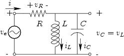
shows a circuit in which a resistor ![]() is in series with the parallel
combination of a capacitor
is in series with the parallel
combination of a capacitor ![]() and inductor
and inductor ![]() .
.
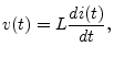
The defining equation of an inductor ![]() is
is
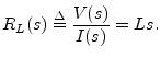
Taking the Laplace transform of both sides gives
Assuming a zero initial current in the inductor at time 0, we have