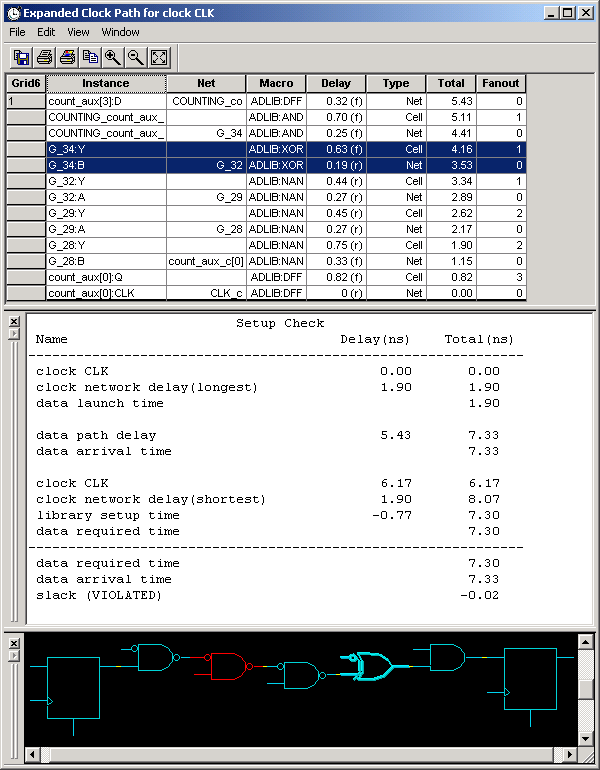
Each path has one or more logic macros and nets that contribute to its total delay. By expanding the path, you can view detailed delay information for that particular path.
Note: With the exception of parallel edges, parallel paths are not available for families that use the pin-to-pin timing model.
To expand a path:
Click the Paths tab.
Select a path set. Paths within that set are displayed in the path grid.
Select the path you wish to expand.
Expand the path by double-clicking the path or right-click and select Expand Path from the context menu, or in the Edit menu, choose Expand Path. The Expanded Path window opens and displays a single path in the Expanded Path Grid and a graphical representation of the path in the Schematic Window.

Timer Expanded Path Window
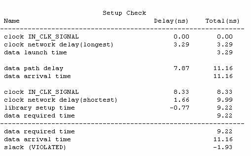
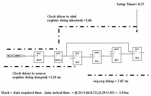
Clock frequency should be the inverse of reg-reg delay plus setup time. However, this is not true with clock skew.
For a pin-to-pin timing model (SX-A, eX, Axcelerator, and ProASIC, ProASICPLUS, and ProASIC3/E), Timer takes into account the register setup and the clock skew (starting in R1-2003) when estimating the maximum clock frequency. However, the setup value is not included in the actual delay reported between the clock pin of a source register and the data pin of a sink register. The Timer Expanded Path window shows Setup Check / Hold Check information. Set the Show option (in Preferences) to Longest to view a detailed analysis of the Setup Check and set the Show option to Shortest to view a detailed analysis of the Hold Check. (These analyses include clock insertion delay information.)
The figures below show the correlation between the Expanded Path Grid (at top), the Setup Check or Hold Check report (at middle) and the Schematic window (at bottom).
Note: The values displayed in the Setup Check / Hold Check report are affected by rounding in calculations, so you may see a very slight discrepancy in the difference between the data required time and the data arrival time (the slack time).


