Introduction
Parts 1 and 2 of these presentations are intended to walk you through
the design and implementation of a Colour Space Convertor, using MathWorks
Simulink and the Xilinx System Generator tool.
Colour Space Conversion is a typical DSP application found in
broadcast-quality video systems.
Most DSP applications that appear complicated in theory, can often be
reduced to a collection of basic functions that are well-suited for
implementation in Xilinx FPGAs, (i.e., adders, subtracters, Multipliers,
and delays). The Xilinx System Generator delivers a library of such
functions that can be used to evaluate bit true/cycle true algorithms with
the MathWorks Simulink Tool. System Generator can export the Simulink
design as a hierarchy of VHDL design files and, where possible, invoke the
Xilinx CoreGenerator to automatically build the bit-true cores inferred in
the Simulink block diagram.
I hope this article delivers a practical introduction to the
Simulink/System Generator design flow whilst also providing some useful
background information on colour and the process of mapping it between
different colour coordinate systems. The coding schemes discussed are
YPBPR, YCBCR and RGB.
What is Colour?
In the physical world, colour does not exist outside of the human head.
The experience of colour is a result of how we interpret the power levels
of radiation found across a range of frequencies in the visible
spectrum.
The human eye has three types of receptors that are sensitive to the
power distribution of these energies. The receptors create stimulus
signals for the brain, which in turn interprets them as colour. The
relationship between perceived colour and Spectral Power Density (SPD) is
the domain of colour scientist. However, from an engineering perspective,
it is important to understand the mechanics of colour in order to create
an electronic system that can capture, transmit, and reproduce it.
In 1931, an organization called the Commission Internationale de
L’Elairage (CIE), carried out investigations to show that human colour
vision is inherently trichromatic and requires three components
(Red, Green, Blue), to mix in an additive manner. The CIE mapped the SPD
of the visible spectrum (400nm -> 700nm), to triple number coordinate
systems that mathematically defines colour space.
There are different coordinate systems for mapping colour space like
there are different coordinate systems for mapping 2D and 3D space. Which
one is used depends on how the feature being mapped is to be expressed
(i.e., Cartesian or polar coordinates for geographical land
mass).
Available coordinate systems mapped by the CIE are CIE XYZ, CIE L*u*v*,
and CIE L*a*b*
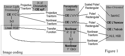
The following diagram is taken from “Technical
Introduction to Digital Video” by Charles Poynton. It illustrates four
groups of coordinate systems used to represent colour: Tristimulus,
Chromticity, Perceptibly Uniform, and Hue-Oriented.

CIE Colour Systems Classified into 4 Groups
Source: Technical Introduction to Digital Video
Author: Charles
Poynton.
The work carried out by the CIE is useful in all areas where
colour reproduction is used. Video, film, and photography all benefit from
the various coordinate systems, but colour science only establishes the
basis for a numerical description of colour. Further transforms are
required to map CIE colour space to coordinates that lend themselves to
practical image coding systems.
Describing a colour in terms of three linear light
components has been adopted as the basis for coding images for digital
video and computer systems.
Tri-stimulus colours must be chosen and then coded into a
perceptually uniform system. (A “perceptually uniform system” is one
where moving from the low end to the high end of a range in incremental
steps causes equal perceptible changes in the system.)
How are CIE XYZ tri-stimulus components derived from a
color image?
Derivation of the CIE XYZ tristimulus values are
complicated to understand, as they contain spectral power density figures
(SPD’s), which are multiplied by a matrix of colour matching functions
(CMF’s) that are derived from experiment! As with a lot of things in video
work, “rules” are defined by experiment, and the quality of results are
subjective.
Can CIE XYZ be used to drive a monitor?
Driving a
real monitor with CIE XYZ signals would work, but would result in poor
colour reproduction.
Constructing the Spectral Power Distribution of any colour using the
addition of three primary SPD’s mapped into a unity colour space
demands that coordinates [0,0,1] [0,1,0] and [1,0,0] be achieved. Since
any colour being mapped contributes to X and Y and Z, the
only way to achieve zero values in an additive system is to add
components with negative value. This would require the use of primary
colours with negative power, (which is not possible), or scale with
colour-matching functions that have negative weighting, (which is also not
practical, as the CIE CMF’s are all positive).
(The problem is a little more complex than this, but the essence is
that the CIE XYZ system of representing colour is not suitable if
full-colour reproduction is required.)
To overcome this problem, the CIE XYZ component signals from the
camera are transformed using a 3x3 matrix to create a set of Linear Red,
Green, and Blue primaries that can define a unity 3-D colour
space:

(Continued on page 2)
 |
|
|
| Pg. 2 |
|
Pg. 3 | |

