|
||
|
| ||
| techXclusives | ||||||||
|
| ||||||||
|
||||||||
| (continued from page 1)
Can Linear RGB be used to drive the monitor? If we applied linearly-coded colour components to a display, equal increments of each component would NOT result in perceived equal increments of colour. Linear RGB values are transformed with another 3x3 matrix multiply to produce a set of primaries that are nonlinear in nature, but which closely match and compensate for the non-linearity of the target monitor. This is known as “gamma correction”, and the gamma-corrected RGB primaries are denoted with a prime symbol (i.e., R’G’B’). In video systems, gamma correction is applied at the camera; it is usual for these signals to be available as the analogue outputs R’G’B’. Can R’G’B’ be used to drive the monitor? Component Analogue RGB SignalsGamma corrected R’G’B’ components are available as analogue signals that require high-stability interfaces with respect to amplitude, level, and timing between the signals. Ideally, all signals carry a sync pulse that assists timing and amplitude monitoring, but the gamma-corrected R’G’B’ format is also implemented with sync on Green only, or on a fourth channel dedicated to sync pulses.
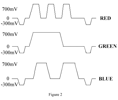
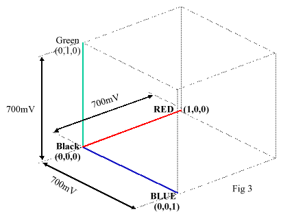
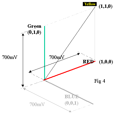
Unity Colour SpaceThe elements that now define our colour space are three signals with a range of 0->700mV, as shown below. These axes define a colour space cube often referred to as “unity colour space,” as the axes are normalised to a magnitude of 1, and any space within the cube can be located as a vector in the form (Red, Green, Blue). i.e. pure red = (1,0,0)
|
||||||||
|
|
||
| Pg. 1 |
|
Pg. 3
|