(continued from page 2)
Computer-Coded “Yellow”
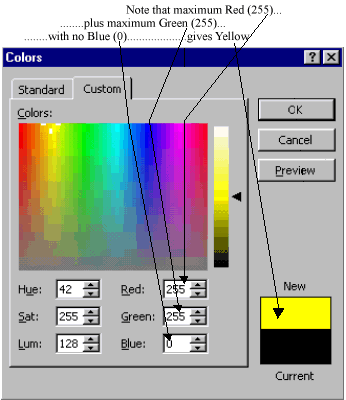
For computer colour coding, 8-bit unsigned binary is used so that a maximum “excursion” is “255”

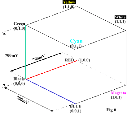
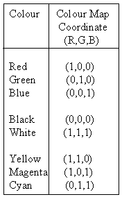
At the extremes of the cube there exist a number of colours constructed from maximum excursions of the three primaries. Those identified below define the boundaries of the RGB colour space cube.


Luminance & Colour difference Coding (Y,B-Y,R-Y)
Whether the final display medium is paper (printing), polymer displays (portable PC’s), or CRT’s (TV), the idea of a quantised piece of 2-D space (the pixel), still holds true.
Each pixel can be expressed with 3 full bandwidth analogue components (R’G’B’); however, transmitting or storing these color components requires a lot of bandwidth.
Reducing this bandwidth is the objective of luminance and colour difference encoding.
CIE tests noted that human vision has less spatial acuity for colour information than it does for brightness information. If R’G’B’ component video is re-coded as a channel of brightness (i.e., luminance -- denoted as Y) and two colour
difference channels ( R-Y and BY), the colour difference data can be spatially reduced without the eye detecting that a change in colour has taken place.
When the brightness content of a colour scene is analysed in terms of its RGB components, Green is shown to carry 60% -> 70% of the brightness information. Because the human eye is more receptive to brightness than to colour, we can
throw away some of the Red and Blue data by coding the difference between Red and Luma and Blue and Luma, instead of Red and Blue themselves. So the colour difference channels are created by subtracting luminance (Y) from the Red and Blue channels,
as this has less impact on the brightness, and Green can be reconstructed from the colour difference channels.
(This basically means that you can throw away some of the Red and Blue data when transmitting the brightness and the colour difference channels!)
The unit R’G’B’ colour space cube is now transformed into a new set of coordinates where the brightness (luminance Y’) is mapped in the vertical axis, and the colour difference channels BY and R-Y can be regarded as colour coordinates.
So how are R’G’B’ coordinates transformed into Y, BY, R-Y coordinates? How do we map gamma-corrected unity colour space into the coordinates that describe a “brightness and colour difference” colour space?
Mapping (R’G’B’) to (Y, BY R-Y)...1
In 1990, the radio-communications group of the International Telecommunications Union made a recommendation that defines how to compute nonlinear video luma from nonlinear Red, Green, Blue primaries. This is now an international standard
(ITU-R BT.601- 4), and is often abbreviated to Rec. 601.
601-compliant luma is defined as:
Y’601 = 0.299R’ + 0.587G’ + 0.114B’ ….. = 1 (Equation 1)
This equation defines how to map R’G’B’ colour space to the luminance on a vertical axis. Y’ is normalised to 1, and the colour difference channels are computed by subtracting this luminance from the Red and Blue channels. (Just
accept it, because that’s the way it is!)
At full excursion, the vector coordinate for Blue is [0,0,1], and the vector coordinate for Luma Y’601 is shown above. Subtracting
Luma from Blue to obtain (B’-Y601 ’) requires a vector subtraction.

So, the colour difference channel ‘Blue minus Luma, (B’-Y’601) is computed from the unity space coordinates (R’G’B’) using the following vector multiplication:

This is repeated for the Red minus Luma colour difference channel.
Mapping (R’G’B’) to (Y, BY R-Y)…2
At full excursion, the coordinate for Red is [1,0,0]. Now, perform the vector subtraction of Luma from the red channel:

So, the R’-Y’ channel transform is computed as follows:

The complete transform of Gamma-corrected RGB (unity colour space) to Rec 601 [Y’ R’-Y’, B’-Y’] (Luma & colour difference colour space) is given as the following matrix multiplication:

If we take the coordinates that define the boundaries of unity colour space and apply them to the above equation, we will map unity colour space into the “Luma & colour difference” colour space that expresses colour more efficiently for transmission.
 |
|
|
| Pg. 1 |
|
Pg. 2
|
Part 2 of Andy Miller's article will lead you through a step-by-step example of this theory, offer more information, and present related examples that utilize the MathWorks Simulink and Xilinx System Generator tools.
Check back on March 26 for PART 2.
|

