The analog transfer function for a peak filter is given by [102,5]
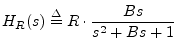
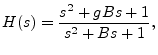
It is easy to show that both zeros and both poles are on the unit
circle in the left-half ![]() plane, and when
plane, and when ![]() (a ``cut''), the
zeros are closer to the
(a ``cut''), the
zeros are closer to the ![]() axis than the poles.
axis than the poles.
Again, the bilinear transform can be used to convert the analog peaking equalizer section to digital form.
Figure 10.16 gives a matlab listing for a peaking EQ section. Figure 10.17 shows the resulting plot for an example call:
boost(2,0.25,0.1);The frequency-response utility myfreqz, listed in Fig.7.1, can be substituted for freqz.
function [B,A] = boost(gain,fc,bw,fs);
%BOOST - Design a boost filter at given gain, center
%        frequency fc, bandwidth bw, and sampling rate fs
%        (default = 1).
%
% J.O. Smith 11/28/02
% Reference: Zolzer: Digital Audio Signal Processing, p. 124

if nargin<4, fs = 1; end
if nargin<3, bw = fs/10; end

Q = fs/bw;
wcT = 2*pi*fc/fs;

K=tan(wcT/2);
V=gain;

b0 =  1 + V*K/Q + K^2;
b1 =  2*(K^2 - 1);
b2 =  1 - V*K/Q + K^2;
a0 =  1 + K/Q + K^2;
a1 =  2*(K^2 - 1);
a2 =  1 - K/Q + K^2;
A = [a0 a1 a2] / a0;
B = [b0 b1 b2] / a0;

if nargout==0
  figure(1);
  freqz(B,A);
  title('Boost Frequency Response')
end
|
![\includegraphics[width=\textwidth]{eps/tboost}](img1363.png) |