 |
Let's start with a very basic example of the generic problem at hand: understanding the effect of a digital filter on the spectrum of a digital signal. The purpose of this example is to provide motivation for the general theory discussed in later chapters.
Our example is the simplest possible low-pass filter. A low-pass
filter is one which does not affect low frequencies and rejects high
frequencies. The function giving the gain of a filter at every
frequency is called the amplitude response (or magnitude
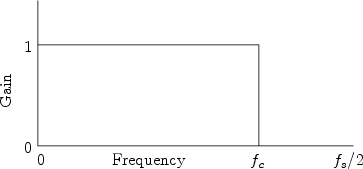
frequency response). The amplitude response of the ideal lowpass
filter is shown in Fig.1.1. It is unity (1) for frequencies
between 0 Hz and the cutoff frequency ![]() Hz, and it is 0 for
all higher frequencies. The output spectrum is obtained by multiplying
the input spectrum by the function shown.
Hz, and it is 0 for
all higher frequencies. The output spectrum is obtained by multiplying
the input spectrum by the function shown.