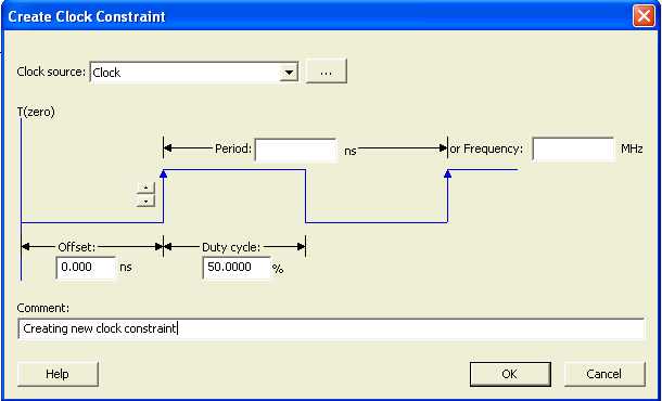
Use this dialog box to enter a clock constraint settings.
It displays a typical clock waveform with its associated clock information. You can enter or modify this information, and save the final settings as long as the constraint information is consistent and defines the clock waveform completely. The tool displays errors and warnings if information is missing or incorrect.
To open the Create Clock Constraint dialog box (shown below) from the SmartTime Constraints Editor, choose Actions > Constraints > Clock.

Create Clock Constraint Dialog Box
Enables you to choose a pin from your design to use as the clock source.
The drop-down list is populated with all explicit clocks. You can also select the Browse button to access all potential clocks. The Browse button displays a Choose Clock Source Pin dialog box.
Instant zero used as a common starting time to all clock constraints.
When you edit the period, the tool automatically updates the frequency value.
The period must be a positive real number. Accuracy is up to 3 decimal places.
When you edit the frequency, the tool automatically updates the period value.
The frequency must be a positive real number. Accuracy is up to 3 decimal places.
Enables you to switch between rising and falling edges and updates the clock waveform.
If the current setting of starting edge is rising, you can change the starting edge from rising to falling.
If the current setting of starting edge is falling, you can change the starting edge from falling to rising.
This number specifies the percentage of the overall period that the clock pulse is high.
The duty cycle must be a positive real number. Accuracy is up to 4 decimal places. Default value is 50%.
The offset must be a positive real number. Accuracy is up to 2 decimal places. Default value is 0.
Enables you to save a single line of text that describes the clock constraints purpose.