A zero-phase filter is a special case of a linear-phase filter
in which the phase slope is ![]() . The real impulse response
. The real impulse response ![]() of a zero-phase filter is even.12.1That is, it satisfies
of a zero-phase filter is even.12.1That is, it satisfies
Note that a zero-phase filter cannot be causal (except in the
trivial case when the filter is a constant scale factor
![]() ). However, in many ``off-line'' applications, such
as when filtering a sound file on a computer disk, causality is not a
requirement, and zero-phase filters are usually preferred.
). However, in many ``off-line'' applications, such
as when filtering a sound file on a computer disk, causality is not a
requirement, and zero-phase filters are usually preferred.
It is a well known Fourier symmetry that real, even signals have real, even Fourier transforms. Therefore,
This follows immediately from writing the DTFT of
A real frequency response has phase zero when it is positive, and a
phase of ![]() radians when it is negative. Therefore, a ``zero-phase
filter,'' as we have defined [
radians when it is negative. Therefore, a ``zero-phase
filter,'' as we have defined [
![]() ] may actually have a
phase response of 0 or
] may actually have a
phase response of 0 or ![]() at each frequency. In practice, the
filter is usually precisely zero-phase in all ``pass bands'', while it
switches between 0 and
at each frequency. In practice, the
filter is usually precisely zero-phase in all ``pass bands'', while it
switches between 0 and ![]() in the stop bands (frequency intervals
where the gain is desired to be zero). A better name, in general,
would be piecewise constant-phase filter. For any real filter,
the constant phase can be either 0 or
in the stop bands (frequency intervals
where the gain is desired to be zero). A better name, in general,
would be piecewise constant-phase filter. For any real filter,
the constant phase can be either 0 or ![]() . Similarly, the term
``linear phase'' could be sharpened to ``linear-phase with
discontinuities by any multiple of
. Similarly, the term
``linear phase'' could be sharpened to ``linear-phase with
discontinuities by any multiple of ![]() radians''.
radians''.
![\includegraphics[width=\twidth ]{eps/remezexa}](img1441.png) |
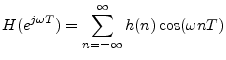
Figure 11.1 shows the impulse response and frequency response of a length 11 zero-phase FIR lowpass filter designed using the Remez exchange algorithm.12.2 The Matlab code for designing this filter is as follows:
N = 11;                % filter length - must be odd
b = [0 0.1 0.2 0.5]*2; % band edges
M = [1  1   0   0 ];   % desired band values
h = remez(N-1,b,M);    % Remez multiple exchange design
The impulse response h is returned in linear-phase form, so it must be left-shifted
Figure 11.2 shows the amplitude and phase responses of the FIR
filter. We see that each zero-crossing in the frequency response
results in a phase jump of ![]() radians. The phase is zero
throughout the pass-band, but in the stop-band, the phase
alternates between zero and
radians. The phase is zero
throughout the pass-band, but in the stop-band, the phase
alternates between zero and ![]() . In practice, very few ``zero-phase
filters'' have a truly zero phase response at all frequencies.
Instead, the phase typically alternates between zero and
. In practice, very few ``zero-phase
filters'' have a truly zero phase response at all frequencies.
Instead, the phase typically alternates between zero and ![]() , as
shown in Fig.11.2. However, the
, as
shown in Fig.11.2. However, the ![]() phase values typically
occur only in the stop-band of the filter, i.e., at frequencies where
the amplitude response is so small that it can be neglected. At
frequencies for which the phase response is
phase values typically
occur only in the stop-band of the filter, i.e., at frequencies where
the amplitude response is so small that it can be neglected. At
frequencies for which the phase response is ![]() , the filter may be
said to be ``inverting'', i.e., it negates the frequency components at
such frequencies.
, the filter may be
said to be ``inverting'', i.e., it negates the frequency components at
such frequencies.
In view of the foregoing, the term ``zero-phase filter'' is only
approximately descriptive. More precise terms would be
0-or-![]() -phase filter, even-impulse-response
filter, or real-frequency-response filter.
-phase filter, even-impulse-response
filter, or real-frequency-response filter.
![\includegraphics[width=\twidth ]{eps/remezexb}](img1443.png)