It turns out that analog allpass filters are considerably simpler
mathematically than digital allpass filters (discussed in
§10.2). In fact, when working with digital allpass filters,
it can be fruitful to convert to the analog case using the bilinear
transform (§G.3.1), so that the filter may be manipulated in the
analog ![]() plane rather than the digital
plane rather than the digital ![]() plane. The analog case
is simpler because analog allpass filters may be described as having a
zero at
plane. The analog case
is simpler because analog allpass filters may be described as having a
zero at
![]() for every pole at
for every pole at ![]() , while digital allpass
filters must have a zero at
, while digital allpass
filters must have a zero at
![]() for every pole at
for every pole at ![]() .
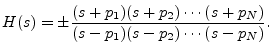
In particular, the transfer function of every first-order analog
allpass filter can be written as
.
In particular, the transfer function of every first-order analog
allpass filter can be written as
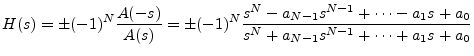
Multiplying out the terms in Eq. (C.14), we find that the numerator
polynomial ![]() is simply related to the denominator polynomial
is simply related to the denominator polynomial ![]() :
:
As an example of the greater simplicity of analog allpass filters
relative to the discrete-time case, the graphical method for computing
phase response from poles and zeros (§8.2) gives immediately
that the phase response of every real analog allpass filter is equal
to twice the phase response of its numerator (plus ![]() when
the frequency response is negative at dc). This is because the angle
of a vector from a pole at
when
the frequency response is negative at dc). This is because the angle
of a vector from a pole at ![]() to the point
to the point ![]() along the
frequency axis is
along the
frequency axis is ![]() minus the angle of the vector from a zero at
minus the angle of the vector from a zero at
![]() to the point
to the point ![]() .
.